


4 – The front panel
YDG2030
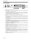
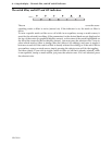
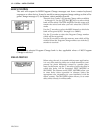
The front panel
From left to right, the controls on the front panel are:
1
INPUT LEVEL
– two concentric rotary controls (inner control is left channel) to adjust the
level of the signal fed into the YDG2030.
2
Level meters – L and R
. These meters come after the A-D convertors in the signal chain. A
“CLIP” indication therefore indicates digital distortion, and the input levels should be
adjusted so that the “CLIP” indicator never lights.
3
Memory
– this 2-digit LED indicator shows the current memory area.
4
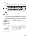
Screen
– this 56 x 128 pixel display gives a graphic representation of the current equal-
ization settings. It is also used to display other settings which you can edit using the
front panel controls.
5
Rotary encoders
– the
F
,
G
and
Q
controls are used primarily for setting the Frequency,
Gain and Q of equalization bands. When editing utility settings, they may also be used
for editing data.
6
NOTCH, HPF and LPF selectors and indicators
– these keys are used to select and dese-
lect the notch filters, HPF and LPF used in an equalization setting. The indicators show
which filters are in effect for this equalization setting.
7
MEMORY keys
– the
[STORE]
,
[RECALL]
,
[^]
and
[%]
keys are used to read and write settings
stored in the 40 memory areas.
8
DISPLAY key
– pressing this key will change the information displayed on the screen –
graphic EQ, notch filter, sweep frequency etc.
9
FLAT key
– pressing this key will return the graphic equalizer to a “flat” setting. The
notch filters, HPF and LPF will not be affected.
0
UTILITY key
– pressing this key will cycle through a range of screens, allowing you to set
up various system parameters for the unit.
A
[L/<]
and
[R/>]
keys
– you can make equalization settings for the left and right channels
independently. These keys allow you to select which channel you are editing. By press-
ing one of these keys, holding it down, and then pressing the other, you can edit the
parameters of both channels simultaneously.
B
BYPASS key
– when pressed, the signal fed into the unit will bypass the internal circuitry,
and will be re-output “as is”.
INPUT LEVEL
0
+10
-∞
LR
L
R
CLIP
-6
-12
-18
-24
-30
-36
-42
MEMORY
FGQ
GRAPHIC
EQUALIZER
NOTCH
1234
HPF LPF
STORE
RECALL
MEMORY
DISPLAY FLAT UTILITY
LR
BYPASS
POWER
ON
OFF
34
5
1
A
6
B
7
2
8
9: