


16 – TUTORIAL – Using the notch filters, and the HPF and LPF
YDG2030
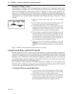
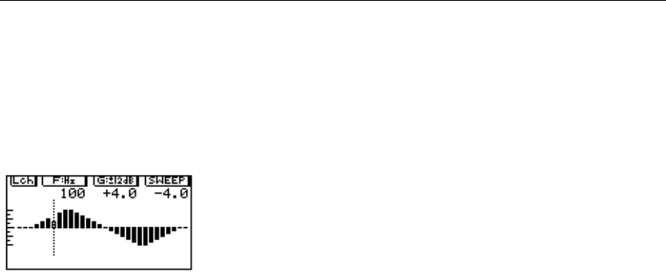
Example II: “Tuning” a room
One method of “tuning” a room (compensating for dead and live frequencies) with a con-
ventional graphic equalizer is to move the faders up and down one at a time while putting
white noise through the sound system. Then, if “ringing” is heard at any particular fre-
quency, you can reduce the gain of that frequency. Likewise, if a particular frequency seems
to get lost, you can increase its gain. This process is simplified greatly with the YDG2030, as
a preset gain or cut can be swept through the entire frequency range using the F rotary
encoder.
1
Enter the sweep screen (see step 1 in the example
above).
2 If you wish to alter both channels simultaneously, link
the channels (see step 2 in the example above).
3 To search for particularly “live” spots, turn the G rotary
encoder to increase the gain by a few dB (experiment to
find the best amount). When this gain is swept, it will
be added to the existing gains at each frequency.
4 While feeding an appropriate signal through the sound
system (pink or white noise is best, if possible), use the
F rotary encoder to sweep the frequency gain you cre-
ated through the entire frequency band, listening for
points that start to ring/feed back. If no ringing occurs,
try increasing the gain setting until it does.
5 Once you know the feedback frequencies, press the
[DISPLAY] key four times to return to the main graphic
equalizer screen, and reduce the gains of those frequen-
cies.
Steps 3, 4 and 5 can be repeated as many times as necessary.
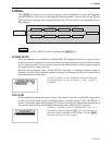
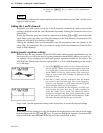
Using the notch filters, and the HPF and LPF
Besides the HPF and LPF, which are shelving high-pass and low-pass filters, respectively,
the notch filters provide very selective gain cuts, with adjustable Q. One of their main uses is
to filter out sounds that occur at specific frequencies, such as 50/60 Hz AC hum, or the high
frequency noise induced by some fluorescent lighting, or lighting dimmers. Of course, to
avoid affecting the original material any more than necessary, try to use the narrowest notch
possible that will remove the offending signals.
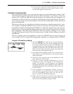
Q is a measure of the resonance of the filter. Basically, the higher the Q, the narrower the
notch. Except for setting the Q, the process for setting the notch filters and the HPF and LPF
is exactly the same (the shelving HPF and LPF don’t have Q).
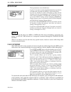
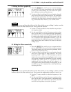
I. Turning the filters on and off individually
1 If you are in any screen other than the two filter screens,
simply press the notch or filter indicator corresponding
to the notch or filter you wish to toggle on/off.
2 If you are in one of the two filter screens, first ensure the
notch or filter is selected for editing (you may need to
press the corresponding selector once to do this), then
press the appropriate selector to toggle it on/off.