


14
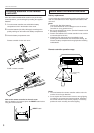
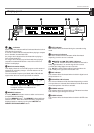
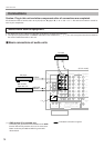
Caution: Plug in this unit and other components after all connections are completed.
All connections must be correct, that is to say L (left) to L, R (right) to R, “+” to “+” and “–” to “–”. Also refer to the owner’s manual for
each of your components.
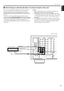
Audio/video source equipment
●
Use RCA type pin plug cables for audio/video units with the exception described later.
●
The output (or input) terminals of YAMAHA audio/video units numbered as 1, 3, 4, etc. on the rear panel must be connected to
the same-numbered terminals of this unit.
PHONO
VIDEO
DVD/LD
TV/DBS
IN
VCR 1
OUT
IN
VCR 2
OUT
ZONE 2
OUT
VIDEO
S VIDEO
DVD/LD
TV/DBS
IN
VCR 1
OUT
IN
VCR 2
OUT
MONITOR
OUT
S VIDEO
1
CD
75Ω
UNBAL.
AM
ANT
FM
ANT
GND
GND
AUDIO SIGNAL VIDEO SIGNAL
OPTICAL
TV/DBSCDCD DVD/LD TAPE/MD
IN
(PLAY)
OUT
(REC)
DVD/LD
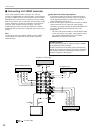
DIGITAL SIGNAL
EXTERNAL
DECODER
INPUT
TAPE/MD
3
4
IN
( PLAY )
OUT
(REC)
MAIN
SUB WOOFER
CENTER
SURROUND
COAXIAL
AUDIO SIGNAL
OUTPUT
GND
OUTPUT
LINE OUT
LINE IN
(U.S.A. model)
Turntable
MD recorder,
Tape deck, etc.
CD player
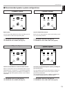
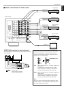
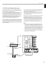
Ⅵ Basic connections of audio units
(*1): GND terminal (For turntable use)
Connecting the ground wire of the turntable to the GND
terminal will normally minimize hum, but in some cases
better results may be obtained with the ground wire
disconnected.
: Indicates the direction of signals.
Connections
PREPARATION
(*1)