


E-3
CONNECTIONS
CONNECTIONS
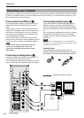
Never
plug in this unit and other equipment until
all connections are completed.
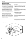
1.
Make connections between this unit and other
components by following the procedure below.
2.
After all connections are finished, check that the
connection cables are correctly connected.
3.
After all connections are completed, plug in this unit and
other equipment.
Note
Also, refer to the owner’s manual for other equipment in the
system.
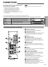
CONNECTIONS
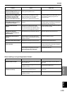
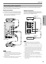
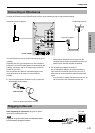
Terminals and their functions
+–
R
L
R L
R L
ANALOG
PC IN
FM ANT
75
Ω UNBAL.
AUX 1
IN
AUX 2
IN
REC
OUT
OUTPUT
SUB
WOOFER
DIGITAL
USB
COAX
IN
OPT
IN
AUX 1
OPT IN
OPT
OUT
PC
SPEAKERS
4Ω MIN.
/
SPEAKER
REAR
+–
R
L
FRONT
CENTER
ANTENNA
1
2
4
5
7
6
3
1 FM antenna connector
This connector is used to connect an FM antenna.
2 SUBWOOFER OUTPUT
This connector can be connected to an optional subwoofer,
such as the Yamaha YST-SW45, for enhanced bass
performance.
3 SPEAKERS outputs
Up to five speakers, such as the Yamaha NS-U40P
speaker system can be connected to the FRONT L, R,
CENTER, REAR L and R terminals. Use speakers whose
impedance is 4Ω or more.
4 ANALOG inputs
These connectors are used to connect to the analog
outputs of a PC sound card, CD player, MD recorder, tape
deck, etc.
5 REC OUT
These connectors are used to connect to the analog inputs
of an MD recorder or tape deck.
6 PC inputs & output (DIGITAL)
USB: If your computer has a USB port, connect it to this
unit, using the supplied USB cable, for remote control of
this unit from your computer.
PC COAX IN/OPT IN: These coaxial and optical
connectors are used to connect to the digital outputs of a
PC sound card, DVD-Video decoder board, etc.
7 Optical input & output (DIGITAL)
AUX 1 OPT IN: This connector is used to connect to an
optical output of a CD player, MD recorder, etc.
OPT OUT: This connector is used to connect to an optical
input of an MD recorder, a DAT deck, etc.
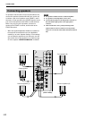
Use commercially available connection cables (except the supplied USB cable).
The color of this unit’s inputs/outputs and pin-plug connection cables to be used for connecting to them are as follows:
White Analog audio signals for the left channel (stereo)
Red Analog audio signals for the right channel (stereo)
Black Analog audio signals (monaural)
Digital audio signals (coaxial)
L
R
L
R
(U.S.A. model)