


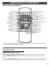
4
CONNECTIONS
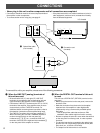
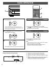
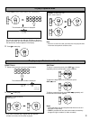
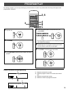
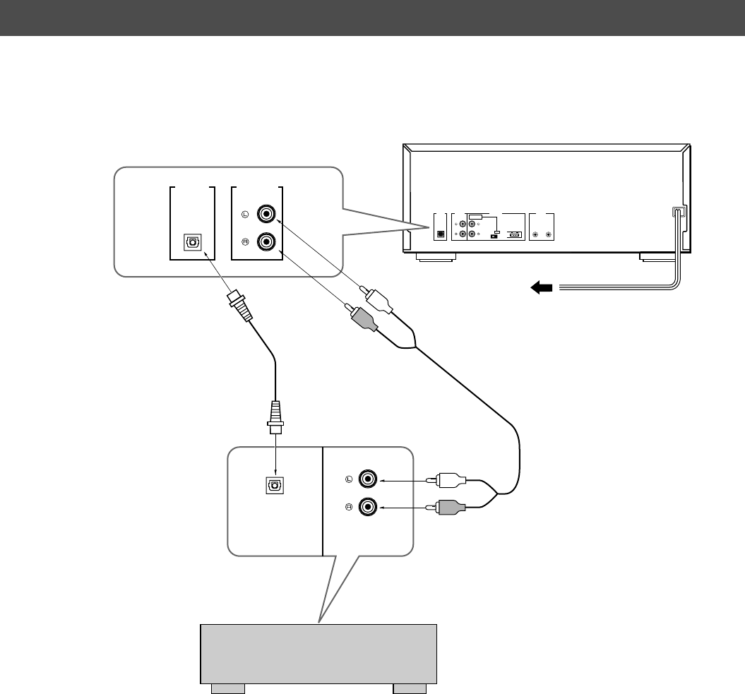
To connect this unit to your amplifier, choose one of the following procedures:
• Connections should be made to the correct input terminals of
the amplifier or other components.
• To connect another unit for relay play, see page 21.
U.S.A model
To AC outlet
1
Connection cord
(included)
2
Optical fiber cable
(not included)
Amplifier
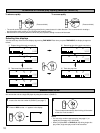
1 When the LINE OUT (analog) terminals of
this unit are used
• Be sure that the left (“L”) and right (“R”) LINE OUT
terminals are connected to the corresponding (left and
right) terminals of the amplifier or other component.
• Connect the “LINE OUT” terminals to the “CD” (or “AUX”)
terminals of the amplifier. If the amplifier does not have
such terminals, use the “TAPE PB” terminals. For
additional details concerning these connections, refer to
the operation instructions of the amplifier being used.
• The LINE OUT terminals of this unit are numbered 1.
When connecting this unit with a YAMAHA amplifier or
receiver whose terminals on the rear panel are
numbered as 1, 2, 3, etc., connect the LINE OUT
terminals of this unit to the input terminals numbered 1
on the rear panel of the amplifier or receiver.
2 When the DIGITAL OUT terminal of this unit
is used
This unit has a DIGITAL OUT (OPTICAL) terminal on the
rear panel.
• Before using the terminal on the rear panel, remove the
terminal’s cover.
• Make the connection from the terminal to the optical
input terminal of an amplifier or other digital audio
component by using a commercially available optical
fiber cable.
* Use an optical fiber cable that conforms to EIAJ
standards. Other cables might not function correctly.
• Be sure to replace the terminal’s cover when the terminal
on the rear panel is not being used, in order to protect
from dust.
• The terminal can also be connected to the optical input
terminal of a DAT (Digital Audio Tape) deck or MD (Mini
Disc) deck, etc., to record a CD directly.
• The output level of this terminal is not variable.
CDDIGITAL IN
OPTICAL
LINE OUT
DIGITAL
AUDIO
OUT
OPTICAL
2ndMAIN
2nd CHANGER
INPUT
CONTROL
RELAY PLAY REMOTE
CONTROL
OUT IN
LINE OUTDIGITAL
AUDIO
OUT
OPTICAL
1
1
• Never plug in this unit or other components until all connections are completed.
• If the placement of this unit creates interference (noise) in
other equipment, such as a tuner, relocate this unit away
from the affected equipment.