


FEATURES ➤ Part names and functions En 11
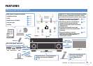
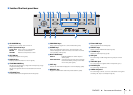
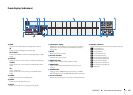
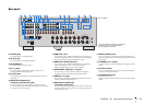
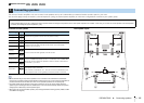
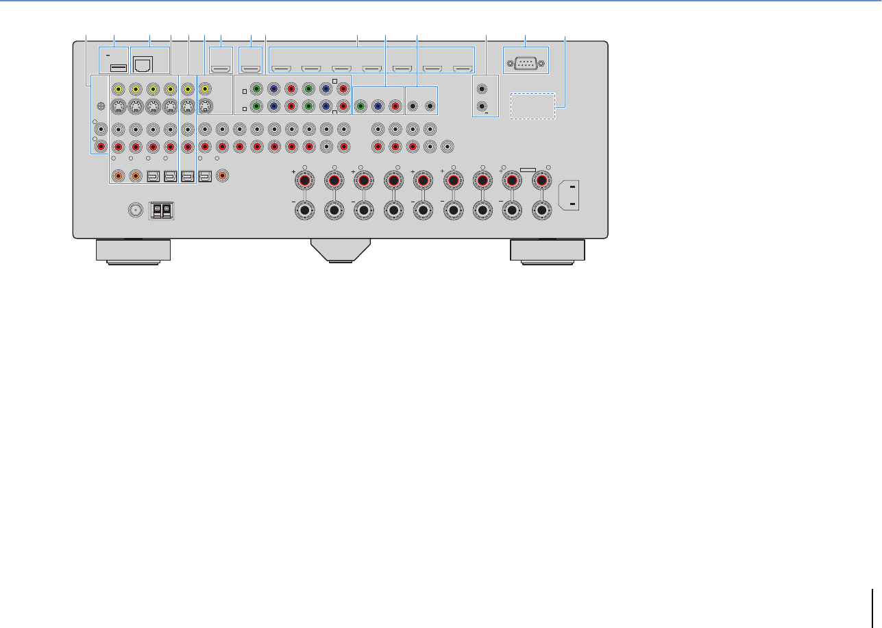
Rear panel
1 PHONO jacks
For connecting to a turntable (p.33).
2 DC OUT jack
For connecting to an optional accessory.
3 NETWORK jack
For connecting to a network (p.37).
4 AV 1–4 jacks
For connecting to video/audio playback devices and
inputting video/audio signals (p.31).
5 AV OUT jacks
For outputting video/audio to a recording device (such as a
VCR) (p.37).
6 MONITOR OUT/ZONE OUT
(composite video/S-video) jacks
For connecting to a TV that supports composite video or
S-video and outputting video signals (p.30) or for connecting
to a Zone2 video monitor (p.81).
7 HDMI OUT 1 jack
For connecting to an HDMI-compatible TV and outputting
video/audio signals (p.26). When using ARC, TV audio signal
can also be input through the HDMI OUT 1 jack.
8 HDMI OUT 2 (ZONE OUT) jack
For connecting to an HDMI-compatible TV and outputting
video/audio signals (p.31), or for connecting to an
HDMI-compatible device used in Zone2 (p.82).
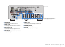
9 COMPONENT VIDEO (AV 1–4) jacks
For connecting to video playback devices that support
component video and inputting video signals (p.32).
0 HDMI (AV 1–7) jacks
For connecting to HDMI-compatible playback devices and
inputting video/audio signals (p.31).
A MONITOR OUT/ZONE OUT
(component video) jacks
For connecting to a TV that supports component video and
outputting video signals (p.30) or for connecting to a Zone2
video monitor (p.81).
B REMOTE IN/OUT jacks
For connecting to an infrared signal receiver/emitter that
allows you to operate the unit and other devices from another
room (p.83).
C TRIGGER OUT 1–2 jacks
For connecting to devices that support the trigger function
(p.38).
D RS-232C terminal
This is a control expansion terminal for custom installation.
Consult your dealer for details.
E VOLTAGE SELECTOR
(General model only)
Selects the switch position according to your local voltage
(p.39).
NETWORKDC OUT
5V
0.5A
( 3
NET
)
MONITOR OUT/
ZONE OUT
HDMI OUT
ARC
(ZONE OUT)
12
HDMI
(1 BD/DVD)
AV 1 AV 2 AV 3 AV 4 AV 5 AV 6 AV 7
TRIGGER
OUT
1
2
RS-232C
YPB PR
YPB PR
YPB PR
MONITOR OUT/ZONE OUT
IN OUT
AV 1
AV 3
REMOTE
COMPONENT VIDEO
A
AV 2
B
C
AV 4
D
AV OUT
R
L
AV 3 AV 4AV 2AV 1
(1 BD/DVD)
OPTICAL
4
OPTICAL
3
COAXIAL
2
COAXIAL
1
PHONO
GND
AC IN
FM
75Ω
ANTENNA
HD Radio
OPTICAL
1
2
AUDIO 4
MULTI CH INPUT
ZONE OUT
AUDIO 3AUDIO 2AUDIO 1
(2 TV)
CENTER
SUBWOOFER
ZONE 2FRONT
SURROUND SUR. BACK
SPEAKERS
CENTER FRONTSURROUND BACKSURROUND
BI–AMP
ZONE 2/F.PRESENCE/
R
5
COAXIAL
6
L R R RL L L
SINGLE
AM
(4 RADIO)
PRE OUT
SUBWOOFER
CENTER
FRONT
SURROUND SUR. BACK
(SINGLE)
EXTRA SP
12V 0.1A
21 3 7 8 D5 6 CA B9:4
E
* The area around the video/audio output jacks is
marked in white on the actual product to
prevent improper connections.
(U.S.A. model)