


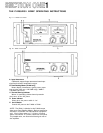
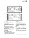
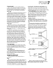
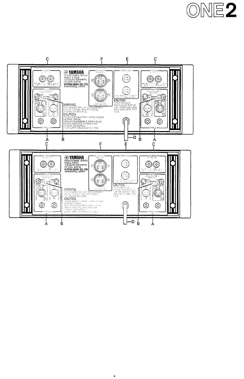
Fig. 2A - P-2200 Rear Panel*
Fig. 2B - P2201 Rear Panel*
A. Input Connectors
The two XLR input connectors on each channel are
unbalanced and are wired in parallel with each other
and with the two phone jacks (tip/sleeve type).
B. Input Polarity Switch
Determines the polarity of the two XLR input
connectors (Pin
2
or Pin
3
"
hot
");
does
not
affect
the
two phone jacks. See diagram on the rear panel.
NOTES:
1. Input impedance is 25k-ohms minimum; +4dB
(1.23V) produces 230 watts output into 8 ohms
(44.7V).
2. Input channels may be parallelled by connecting
them together with phone to phone or XLR to XLR
cables as shown on Page SIX 7.
3. Input transformers for matching or isolation,
should be located several inches from the P-2200 or
P2201's
power transformer
for
maximum
hum
rejection.
C. Output Connectors
Standard 5-way binding posts (3/4" spacing) accept
banana plugs or direct-wired connections.
NOTES:
1. Maximum power output into 8 ohms is 230 watts;
power output rises at lower impedances.
2. Protection circuitry towers power output when
load impedance falls below 2.5 ohms.
D. AC Power Cord
For the U.S. and Canadian models, the P-2200/2201
require 117 VAC 50 or 60 Hz line (105 V min., 135 V
max.; 8 amps max. at 120 volts).
For the Australian model: 240V AC 50 or 60 Hz.
For other territories' models, an internal voltage
selector (220 V/240 V switchable) is provided near the
rear panel. In this case 220 V is factory-preset. If you
want
to
change
into
240
V
line,
consult
your
nearest
Yamaha dealer.
E. Fuses
7 amp, 125 volt (x 2), type AGC (3AG); U.S. and
Canadian models only. 4 amp, 250 volt (x 2); other
territories models. Fuses should always be replaced
with
same
size
and
type.
If
the
fuses
blow
consistently,
the amplifier should be checked by a qualified Yamaha
service technician.
F. AC Accessory Outlets
These convenience outlets are made for low power
cooling fans. Not provided in certain areas.
The rear panels shown here are subject to U.S. specifications.