


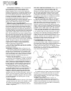
Regarding Input Impedance and Terminations
There is sometimes a misunderstanding regarding the
nature of matching or bridging inputs, the use of termi-
nating resistors, and the relationship between actual
input impedance and nominal source impedance. Most
electronic outputs work well when "terminated" by an
input (connected to an input) having the same or a
higher actual impedance. Outputs are usually overloaded
when terminated by an impedance that is lower than the
source impedance. When the actual input impedance of
the following device is nearly the same impedance as the
source, it is known as a "matching" input. When the
input of the following device is ten times the source
impedance, or more, the input is considered to be a
"
bridging"
input.
There
is
hardly
any
loss
of signal
level when an input bridges the source device, but a
matching input may cause a loss of 3 to 6dB in level.
Such losses, however, are normal and usually present
no problem.
It seldom is necessary to place a 600 ohm "termin-
ating resistor" across any high impedance input (the
P-2200's input can be considered to be high impedance).
In fact, most 600-ohm outputs operate normally when
bridged by a high impedance; it is as though no load
were connected to the source device.
The only instance where a terminating resistor may
be required is when the manufacturer of the source
device specifically states that a terminating resistor is
necessary. In such cases, there is usually a special type
of output transformer in the source device, or the device
is constructed primarily of precision, passive com-
ponents (no transistors or tubes), such as a passive
equalizer. In these cases, the terminating resistor assures
optimum frequency response in that device. Input
terminating resistors are not needed for the P-2200 to
operate correctly. If a 150 ohm or 600 ohm resistor is
specified for the source device, it should be installed at
the end of the cable nearest the P-2200 in order to
minimize possible hum, noise or signal losses in the cable.
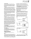
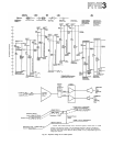
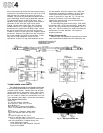
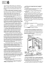
Fig. 36A - The Actual Voltage reaching the Load Device
is given by the Formula: (also see Appendix)
Fig. 36B - Where to Insert a Termination Resistor when one
is required.
CABLING AND IMPEDANCE MATCHING
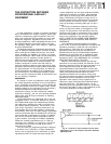
Attenuation Pads
A "pad" is a resistive network that lowers the level in
an audio circuit. The most common professionally used
pads are "T-pads" and "H-pads." T-pads unbalance true
balanced lines (and floating lines), but work well in
unbalanced circuits. H-pads are best for balanced or
floating lines, but should not be used in an unbalanced
circuit since they will insert a resistance in the return
lead (ground). For a discussion of other types of pads,
refer to the AUDIO CYCLOPEDIA by Howard M.
Tremain (Pub. Howard W. Sams).
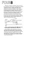
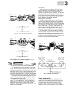
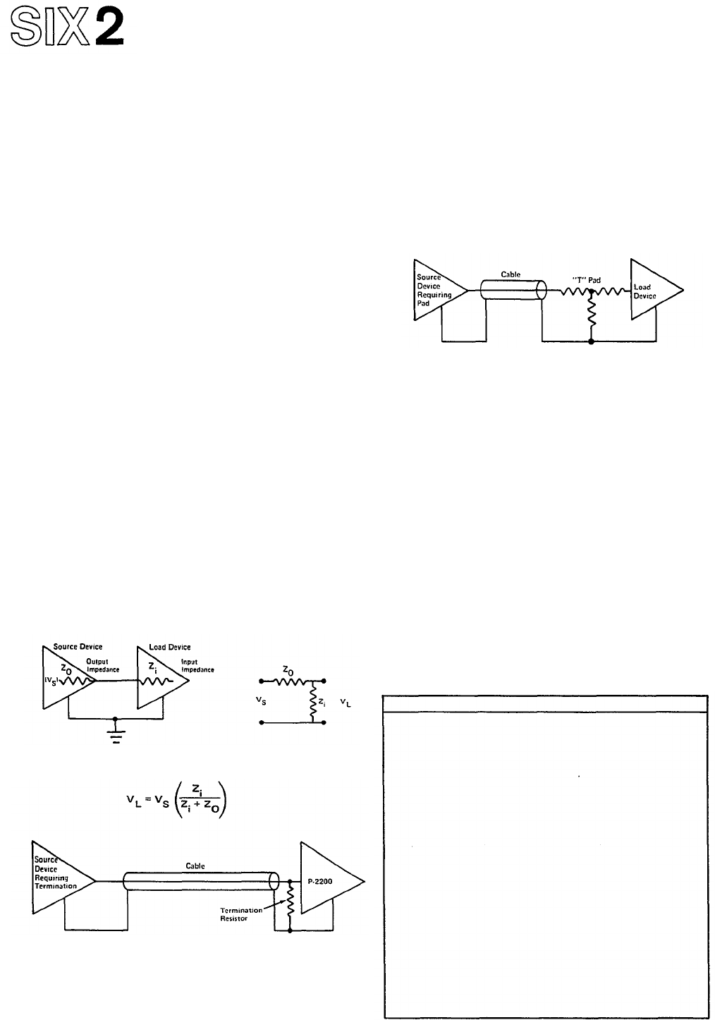
Fig. 37 - Where to Install a Pad when one is required.
Always install a T-pad near the input of the device it
feeds, with as short a length of cable as possible on the
low level side of the pad. This maintains a high signal
level in the longer transmission cable, minimizing any
induced hum and noise.
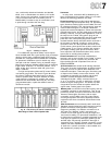
The low impedance pad values illustrated in Figure 38
are designed for 600-ohm lines. Commercially manu-
factured pads are available; consult your Yamaha dealer.
When connected between a 600-ohm or lower source
and a 600-ohm or higher termination, pad attenuation
values
will
remain
fairly
accurate. For higher impedance
circuits, resistor values must be changed. A 600-ohm pad
inserted in a high impedance circuit may overload the
device feeding the pad (the source device). Multiply the
given values by the output impedance of the source
device, and divide that answer by 600 to achieve the
desired value. The high impedance values listed for the
T-pads in Figure 38 are close approximations of average
hi-fi pads, based on 10,000-ohm nominal impedances.
For low level circuits, use 1/4 watt resistors. For out-
puts with continuous sine wave levels above +24dBm,
use 1/2 watt resistors; for continuous sine wave levels
dB Loss
R1 T (ohms)
R1 H (ohms)
R2
0.5
1.0
2.0
3.0
4.0
5.0
6.0
7.0
8.0
9.0
10
12
14
16
18
20
22
24
26
28
30
32
34
36
38
40
50
300
560
1100
1710
2200
2700
3300
3900
4300
4700
5100
6200
6800
7500
7500
8200
8200
9100
9100
9100
9100
9100
10k
10k
10k
10k
10k
16
33
68
100
130
160
200
220
270
270
300
360
390
430
470
510
510
510
560
560
560
560
560
560
560
560
620
150
300
560
820
1100
1500
1600
2000
2200
2400
2700
3000
3300
3600
3900
3900
4300
4300
4700
4700
4700
4700
4700
4700
4700
5100
5100
8.2
18
33
51
68
82
100
110
130
150
150
180
200
220
220
240
240
270
270
270
270
300
300
300
300
300
300
180k
82k
43k
27k
22k
16k
13k
11k
9100
8200
6800
5100
4300
3300
2700
2000
1500
1300
1000
820
620
510
390
330
240
200
62
10k
5.1k
2.7k
1.6k
1.2k
1k
820
680
560
470
430
360
240
200
150
120
91
75
62
47
36
30
22
18
15
12
3.6
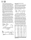
Fig. 38 - Attenuation Pad Construction and Resistor Values
for High Impedance (10K-ohm) and Low Impedance (600 ohm)
[shaded area) circuits.