


HUM AND NOISE
Hum or noise from a power amplifier disrupts a
program, and is irritating to a listener. Hum and noise
could be considered a form of distortion. The P-2200's
hum and noise are so low that they are completely
inaudible under any normal listening circumstances.
RISE TIME
Rise time is a measurement of the amount of time an
amplifier requires to respond to a square wave at a
specified frequency. The rise time of an amplifier is an
indication of its frequency response. A fast rise time
corresponds to a wide frequency response. The P-2200's
rise
time
specification
is
measured
with
a
1000Hz
square
wave output signal of one volt peak-to-peak amplitude.
The rise time is the time the amplifier requires to change
from 10% (0.1 volt) to 90% (0.9 volt) of its output. To
improve measurement accuracy, the first and last 10%
are normally not included in the test (any slight non-
linearities that occur in the test signal or the amplifier
could lead to measurement error).
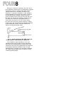
SLEW RATE
Slew rate is a measure of a power amplifier's ability
to follow a fast rising waveform at higher frequencies
and higher power outputs than the rise time measure-
ment. The P-2200's slew rate is measured with a 200kHz
square wave input signal, at 175 Watts output power
into 8 ohms.
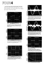
It might seem reasonable to assume that the fastest
slew rate for an audio waveform occurs at 20kHz.
However, this is not the case. When one frequency is
superimposed upon another, the combined waveform
has a slew rate that is greater than the slew rate of
either signal by itself. The actual value of the slew rate
of one of these waveforms (or any waveform) depends
not only on the frequency, but on the amplitude of the
waveform as well. Thus, the criteria for a good slew rate
specification, which indicates that an amplifier can
reproduce these combination waveforms, varies with
the maximum power output capability of the amplifier.
The higher the power, the higher the required slew rate.
With a 45 volts/microsecond slew rate, the P-2200 can
easily reproduce even the most extreme audio wave-
forms at its full power output.
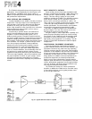
INPUT IMPEDANCE
The input impedance of the P-2200 is high enough
to allow it to be used with most semi-pro devices, or to
be
used
as
a
"bridging"
load
for
a
600-ohm source.
Page SIX 2 details input impedance and level matching
for the P-2200.
INPUT SENSITIVITY
The P-2200's input sensitivity indicates the input
drive voltage needed for the P-2200 to produce its
rated output of 230 watts into 8 ohms (input attenua-
tors are adjusted to maximum clockwise rotation for
minimum attenuation).
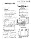
PROTECTION CIRCUITS AND
THERMAL SPECIFICATIONS
See the discussions under INSTALLATION, on
Page SIX 13.
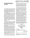
GAIN
Gain is the ratio of the P-2200's output voltage to its
input voltage. Maximum gain occurs when the input
attenuators are set for minimum attenuation. If the input
and output voltage are specified in dB, the voltage gain is
equal to the difference of the two dB numbers. As stated
under INPUT SENSITIVITY, an input voltage of +4dB
(1.23 volts) produces an output power of 230 watts into
an 8-ohm load. 230 watts into 8 ohms implies an
output voltage of 43 volts which corresponds to +35dB
(referenced to 0.775 volts, as used in this manual). The
voltage gain of the P-2200, with its input attenuators set
for minimum attenuation, then, is 31dB [(+35dB)-(+4dB)].
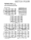
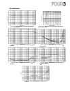
OUTPUT IMPEDANCE (Refer to Figures 9 & 20)
The output impedance of the P-2200 is extremely
low. Thus, within its operating limits, the P-2200 is a
good approximation of a perfect voltage source and will
deliver increasing power levels into lower impedance
loads in a linear fashion according to Ohm's law. The
Appendix discusses Ohm's law and the concept of a
perfect voltage source.
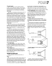
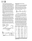
DAMPING FACTOR
Damping factor is a term that is derived by
dividing the load impedance (speaker or other load) by
the amplifier's output impedance. Thus, a high damping
factor indicates a low output impedance at a specified
load.
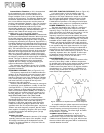
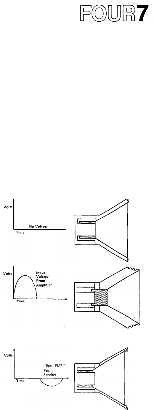
The cone/voice-coil assembly of a loudspeaker gains
inertia during its back and forth movements. This
inertia can cause it to "overshoot," that is, to continue
movement in one direction, even when the amplifier
is trying to pull it back in the other direction. An
amplifier with a low output impedance can "damp"
(reduce) unwanted loudspeaker motions, as explained
below.
Fig. 30A - Speaker Cone at Rest
Fig. 30B - Speaker Cone moved outward by Postive-Going
Voltage from Amplifier.
Fig. 30C -
Voltage from Amplifier has dropped to Zero but
Speaker Cone has moved back PAST its rest position (overshoot)
and is producing a voltage of its own: "Back EMF"