


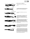
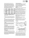
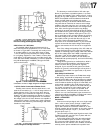
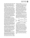
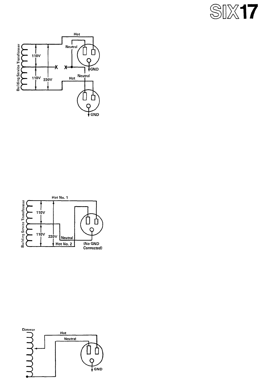
Fig. 62D - 110V AC Outlets with Lifted Neutral. Outlets will
operate with voltage varying from 0 to 220V AC creating shock
hazard and causing possible equipment damage.
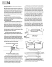
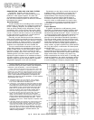
220V AC on 110V AC Outlet
It is possible (albeit, illegal and dangerous) for a
220V AC circuit to be connected to a 110V AC outlet
as shown in Figure 62E. Fortunately, this rarely occurs.
In an older building, it may have been done to allow
110V AC wiring to carry the 220V AC voltage needed
to run lighting equipment. If the P-2200, or some other
audio device, is plugged into such an outlet, the AC line
fuses will blow almost immediately, but some equipment
may still be damaged. In addition, this type of outlet
poses a shock hazard.
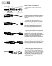
Fig. 62E - 110V AC Outlet with a 220V AC Circuit
connected to it. This is a highly dangerous and illegal connection.
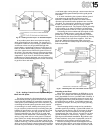
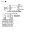
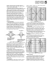
110V AC Outlet Connected to Dimmer Circuit
Possibly more common than the 220V-wired 110V
outlet is the connection of a 110V AC stage outlet to a
lighting dimmer circuit. This may have been done to
allow lighting to be controlled on stage from a remote
location. An outlet connected to a dimmer is a poor, if
not illegal, practice and the light dimmer can decrease
the voltage in the circuit. Some dimmers are capable of
raising the AC voltage. In either case, audio equipment
connected to the circuit may suffer damage, and shock
hazards are also possible.
Fig. 62F - 110V AC Outlet connected to a Light Dimmer
Circuit, a dangerous and illegal connection.
The best way to avoid all kinds of AC mains pro-
blems, for permanent or portable systems, is to check
the voltage and polarity of the outlet yourself - before
plugging in any audio equipment. Three wire AC circuit
testers are available at most hardware and electrical
stores, and
will
allow
easy
polarity
and
ground
continuity checking of all outlets. While these testers
may show that an outlet has an extreme over-voltage
condition (the tester may burn out), the tester may not
show
less
extreme,
but
still
serious, over-voltage condi-
tions. Also, even though such testers may display
continuity to ground at the third pin of the AC outlet,
the resistance in the ground may still be high enough to
warrant the use of a separate earth ground. Thus, it is
also a good idea to carry a small voltmeter for verifying
the actual voltage at an AC outlet, and to establish a
direct path to earth ground that does not rely on the
AC mains. Some commercially available AC plug
strips
have
an
AC voltmeter
built
in,
or
you
can
install
a panel mount meter that reads voltage before equip-
ment is connected to the AC circuits in an equipment
rack.
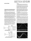
Even if the voltage and polarity of the AC outlet are
correct, the line may be "soft," that is, it may not be
capable of sustaining proper voltage under load. Monitor
the AC line voltage when the P-2200 is operating near
full power. If the AC line voltage falls below the
minimum rated for the P-2200 (105 volts RMS), the
P-2200
will
not
operate
properly,
and could conceivably
sustain damage.
Lifting the AC ground to an audio device, while it
may solve some noise problems, also lifts the safety
feature for which the AC ground was originally
designed.
If
you
must
lift
the AC
ground,
be
certain
that the AC ground is carried through to that piece of
equipment via the shield of a signal cable, or by some
other means.
Other Safety Considerations
While it may seem obvious, the P-2200 does weigh
44 Ibs (20kg), and should be adequately mounted to
prevent it from falling onto other equipment or people.
Also,
while
less
obvious, the
speaker
output
terminals
of the P-2200 can deliver as high as 57 volts RMS, and
under certain conditions, this could present a shock
hazard. It is common practice in the audio industry to
use
"male"
connectors
to
carry
output
signals,
and
"female" connectors for inputs. For speaker level
signals, however, it may be safer to reverse this con-
vention, or to use "recessed male" type connectors as
outputs to avoid the possibility of coming into contact
with the high voltage output of the P-2200.
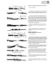
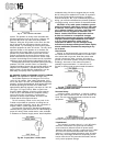
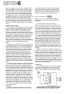
MONO OPERATION
Connections
Connect a mono input signal, such as a single output
from a mixer or other source, through a splitter trans-
former to both of the P-2200's inputs as shown in
Figure 63A. Switch the POLARITY SWITCH on one
channel opposite that of the switch on the other channel
(one switch grounds pin 2 to pin 1; the other switch
grounds pin 3 to pin 1).
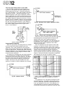
This connection provides equal signals to each of the
P-2200's inputs with one input out of phase with the
other (reversed in polarity).
Connect the speaker load to the two red terminals
(+) on the P-2200's outputs as shown in Figure 63B.
Do not connect either speaker wire to ground as this
would short out one channel of the P-2200, and would
severely cut the power available to the speaker load.