7
English
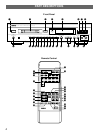
DIGITAL OUT
OPTICAL
DIGITAL IN DIGITAL OUT
OPTICAL OPTICAL
L
L
R
R
DIGITAL
OPTICAL
OUT
1
2
ANALOG
IN OUT
(PLAY)(REC)
34
IN
L
L
R
R
PLAY
REC
3
4
LR
DIGITAL
OPTICAL
OUT
1
2
ANALOG
IN OUT
(PLAY)(REC)
34
IN
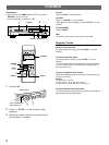
• Connections should be made to the correct input/output terminals on the other component.
• Also refer to the owner’s manual supplied with the component you are connecting.
• If the placement of this unit causes noise in other equipment, such as a tuner, move them farther apart.
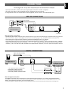
CONNECTIONS
Do not plug in this unit (or other components) until all connections are complete.
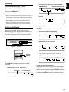
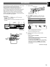
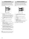
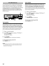
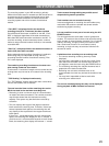
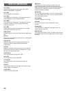
ANALOG CONNECTIONS
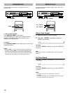
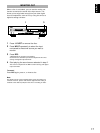
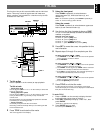
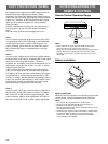
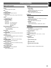
DIGITAL CONNECTIONS
Notes for analog connections
• The white plug on the audio connecting cords corresponds to the L (left) channel and the red plug corresponds to the R (right) channel.
Be sure to connect L (left) to L and R (right) to R. Also make sure that the plugs are fully inserted and that the connection is firm.
• The LINE OUT jacks on the MD recorder should be connected to the MD PLAY jacks on your amplifier.
The LINE IN jacks on the MD recorder should be connected to the MD REC jacks on your amplifier.
• The LINE OUT terminals on this unit are numbered 3 and the LINE IN jacks are numbered 4. When connecting this unit to a YAMAHA
amplifier or receiver whose terminals are numbered 1, 2, 3, 4 ... (etc.), connect this unit’s LINE OUT terminals to the input terminals
numbered 3 and connect this unit’s LINE IN terminals to the output terminals numbered 4 on the rear panel of the amplifier or receiver.
Audio connecting cords (included)
To AC outlet
To AC outlet
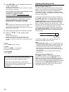
Notes for digital connections
• The DIGITAL IN terminals can be connected to any component with an optical output so you can make direct digital recordings.
• The DIGITAL OUT terminal can be connected to a any component with an optical input so you can output digital audio from an MD.
• Before making OPTICAL connections, remove the terminal cover(s).
• In order to protect the terminals from dust, be sure to attach the terminal covers when the optical terminals are not being used.
*Optical fiber cable
*Optical fiber cable
Amplifier/Receiver
Amplifier/Receiver
(or MD/DAT recorder)
with optical IN/OUT
Optical fiber cable (included)
CD player (etc.) with
optical OUT
* One optical fiber cable is included with
the MDX-595. Additional OPTICAL
connections should be made using
commercially available optical fiber cables.