


14
CONNECTIONS
Connecting video components
Refer to the connection examples on the next page.
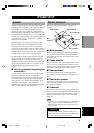
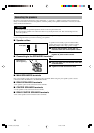
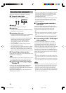
■ Types of video jacks
There are three types of video jacks as follows:
1 VIDEO jack
Conventional composite video signal.
2 S VIDEO jack
Transmits color and luminance separately and achives
high-quality color reproduction.
3 COMPONENT VIDEO jacks
Transmit color difference (P
B
/C
B
, P
R
/C
R
) and luminance
separately and provide the best quality picture.
• Each type of video jack works independently. Signals
input through the composite video, S-video and
component jacks are only output through the
corresponding composite video, S-video, and
component jacks.
• Use a commercially available cable specified for
connecting each type of jacks.
•
The description of the component video jacks may differ
depending on the component (e.g. Y, C
B
, C
R
/Y, P
B
, P
R
/Y,
B-Y, R-Y etc.). When using these jacks, refer also to the
operation instructions for the component being connected.
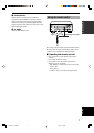
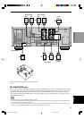
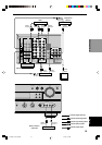
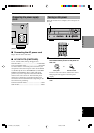
■ Connecting a video monitor
Connect the video input jack on your video monitor to the
MONITOR OUT VIDEO jack.
Note
• If you connect this unit with a source component using S-video
(or Component video) jacks, you also need to connect your
video monitor using S-video (or Component video) jacks.
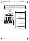
■ Connecting a DVD player/digital
TV/cable TV
Connect the optical digital audio signal output jack on
your component to the DIGITAL INPUT jack and
connect the video signal output jack on the component to
the VIDEO jack on this unit.
Then connect AUDIO jacks on your component to the
AUDIO jacks on this unit.
y
• If your video component has an S-video output or component
video output, connect the S-video signal output jack on the
component to the S VIDEO jack or connect the component
video signal output jacks on the component to the
COMPONENT VIDEO jacks.
• The AUDIO jacks are available for a video component which
does not have optical digital output jack. However, multi-
channel reproduction cannot be obtained with audio signals
input from AUDIO jacks.
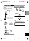
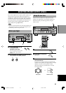
■ Connecting a game console or
camcorder
Connect the optical digital audio signal output jack on
your video component to the OPTICAL jack on the front
panel and connect video signal output jack on the
component to the VIDEO jack on the front panel.
y
• If your video component has an S-video output, connect the S-
video signal output jack on the component to the S VIDEO
jack.
• The AUDIO jacks are available for a video component such as
a camcorder which does not have optical digital output jack.
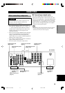
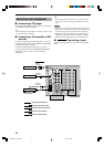
■ Connecting a VCR or DVR (digital
video recorder)
Connect the audio signal input jacks on your video
component to the AUDIO OUT jacks and connect the
video signal input jack on the video component to the
VIDEO OUT jack on this unit for picture recording.
Connect the audio signal output jacks on your component
to the AUDIO IN jacks and connect the video signal
output jack on the component to the VIDEO IN jack on
this unit to play a source from your recording component.
Second VCR or digital video recorder can be connected
using VCR 2/DVR jacks.
y
• If your video component has an S-video input, connect the S-
video signal input jack on the component to the S VIDEO OUT
jack.
• If your video component has an S-video output, connect the S-
video signal output jack on the component to the S VIDEO IN
jack.
Notes
• Once you have connected a recording component to this unit,
keep its power turned on while using this unit. If the power is
off, this unit may distort the sound from other components.
• S-video and component video signals pass independently
through this unit’s video circuit. Make sure to connect this unit
to both a source component and a recording component using
the video jacks of the same system.
COMPONENT VIDEO
P
R
/C
R
P
B
/C
B
Y
VIDEOS VIDEO
2 1 3
0103V630_9-18_EN(GB) 1/11/02, 7:40 PM14