


11
English
INTRODUCTION
PREPARATION
BASIC OPERA-
TION
ADVANCED
OPERATION
ADDITIONAL
INFORMATION
APPENDIX
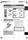
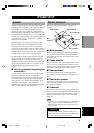
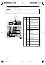
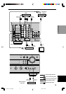
SPEAKER SETUP
DIGITAL
OUTPUT
SPEAKERS
MAIN
MAIN
DIGITAL
INPUT
6CH INPUT
CD
CD
IN
(PLAY)
OUT
(REC)
DVD
D-TV
/CBL
DVD
OUT
VCR 1
VCR 2
/VDR
MD
/CD-R
D-TV
/CBL
OUT
IN
DVD
IN
FM
ANT
AM
ANT
GND
75
UNBAL.
OPTICAL
D-TV/CBL
MD/CD-R
MD/CD-R
OPTICAL
COAXIAL
S VIDEO VIDEO
OUTPUT
S VIDEO
MONITOR OUT
MONITOR
OUT
VIDEO
VIDEO
TUNER
YP
B
/C
B
P
R
/C
R
COMPONENT VIDEO
AUDIOAUDIO
MAIN
CENTER
SUB
WOOFER
SUB
WOOFER
SURROUND
CENTER
CENTER
AC OUTLETS
REAR
CENTER
REAR CENTER
OUTPUT
L
R
L
R
L
R
L
L
L
R
R
A
–
–
+
+
–
+
–
+
–
+
B
REAR
(SURROUND)
REAR
(SURROUND)
IMPEDANCE SELECTOR
SET BEFORE POWER ON
R
MIN. /SPEAKER
MIN. /SPEAKER
MIN. /SPEAKER
MIN. /SPEAKER
MIN. /SPEAKER
MIN. /SPEAKER
MIN. /SPEAKER
MIN. /SPEAKER
MIN. /SPEAKER
MIN. /SPEAKER
:4
:8
:6
:6
:6
8
16
8
8
8
MAIN
A OR B
A+B
CENTER
REAR CENTER
REAR
MAIN A OR B
A+B
CENTER
REAR CENTER
REAR
:
:
:
:
:
1
56
7
3
2
4
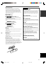
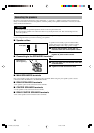
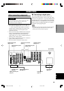
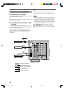
Subwoofer
system
Rear center
speaker
Main B speaker
Center
speaker
Right
Rear speaker
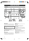
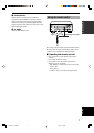
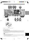
■ SUBWOOFER jack
When using a subwoofer with built-in amplifier, including the YAMAHA Active Servo Processing Subwoofer System,
connect the input jack of the subwoofer system to this jack. Low bass signals distributed from the main, center and/or
rear channels are directed to this jack in accordance with your SPEAKER SET selections. The LFE (low-frequency
effect) signals generated when Dolby Digital or DTS is decoded are also directed to this jack in accordance with your
SPEAKER SET selections.
Notes
• The cut-off frequency of the SUBWOOFER jack is 90 Hz.
• If you do not use a subwoofer, designate the signals to the main left and right speakers by changing the setting of SPEAKER SET
item “1E BASS” on the SET MENU to MAIN.
• Use the control on the subwoofer to adjust its volume level. It is also possible to adjust the volume level by using this unit’s remote
control (see “ADJUSTING THE LEVEL OF THE EFFECT SPEAKERS” on page 51).
Right Left
Main A speaker
Right Left
Left
1
2
4
3
7
6
5
The diagram shows the speaker layout in the listening
room.
(RX-V630RDS)
0103V630_9-18_EN(GB) 1/11/02, 7:40 PM11