


Front and Rear of Unit
Rear Panel
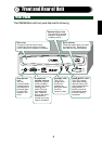
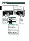
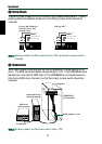
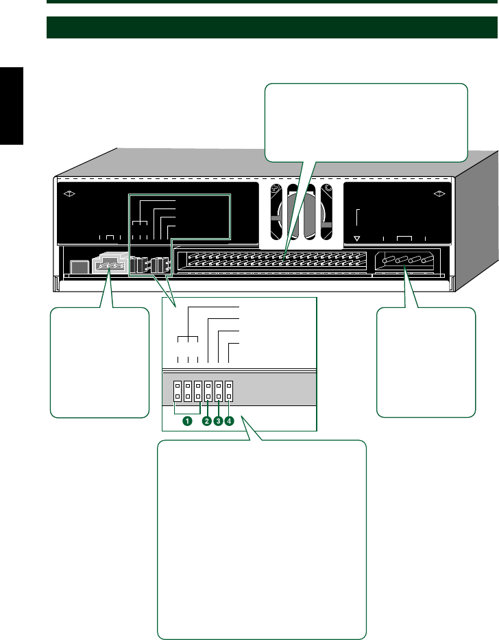
The CRW8824S drive’s rear panel features the following:
AUDIO OUT
connector
Connect one end
of the supplied 4-
pin audio cable
to this and the
other end to your
computer’s sound
card or built-in
audio.
DC INPUT
connector
Insert the power
connector from
your computer’s
power supply in
this socket to
feed power to the
drive.
SCSI connector
Insert the connector of the SCSI ribbon
cable here. Make sure you align the
red line of the ribbon cable with pin 1 of
the drive’s connector, marked “SCSI
INTERFACE CONNECTOR 1.”
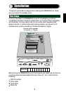
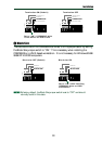
ID SELECT
PARITY
TERMINATOR
BLOCK SIZE
124
1 ID SELECT jumper switches
Set these switches using black plastic
shunts in order to manually assign a SCSI
ID number for the drive.
2 PARITY jumper switch
Set this switch using a black plastic shunt
in order to enable parity checking.
3 TERMINATOR jumper switch
Set this switch using a black plastic shunt
in order to enable the drive’s built-in SCSI
termination.
4 BLOCK SIZE jumper switch
Set this switch using a black plastic shunt
in order to set the block size to 512 bytes
per sector.
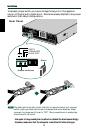
AUDIO OUT
RLG
ID SELECT
PARITY
TERMINATOR
BLOCK SIZE
124
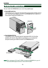
AUDIO OUT
connector
Connect one end
of the 4-pin audio
cable to this and
the other end to
your computer’s
sound card or
built-in audio.
DC INPUT
connector
Insert the power
connector from
your computer’s
power supply in
this socket to
feed power to the
drive.
SCSI connector
Insert the connector of the SCSI ribbon
cable here. Make sure you align the
red line of the ribbon cable with pin 1 of
the drive’s connector, marked “SCSI
INTERFACE CONNECTOR 1.”
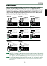
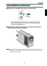
DC INPUT
+
5V G
+
12
V
1
SCSI
INTERFACE
CONNECTOR
7