


2
Chapter 1—Introduction
CP2000—Owner’s Manual
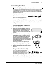
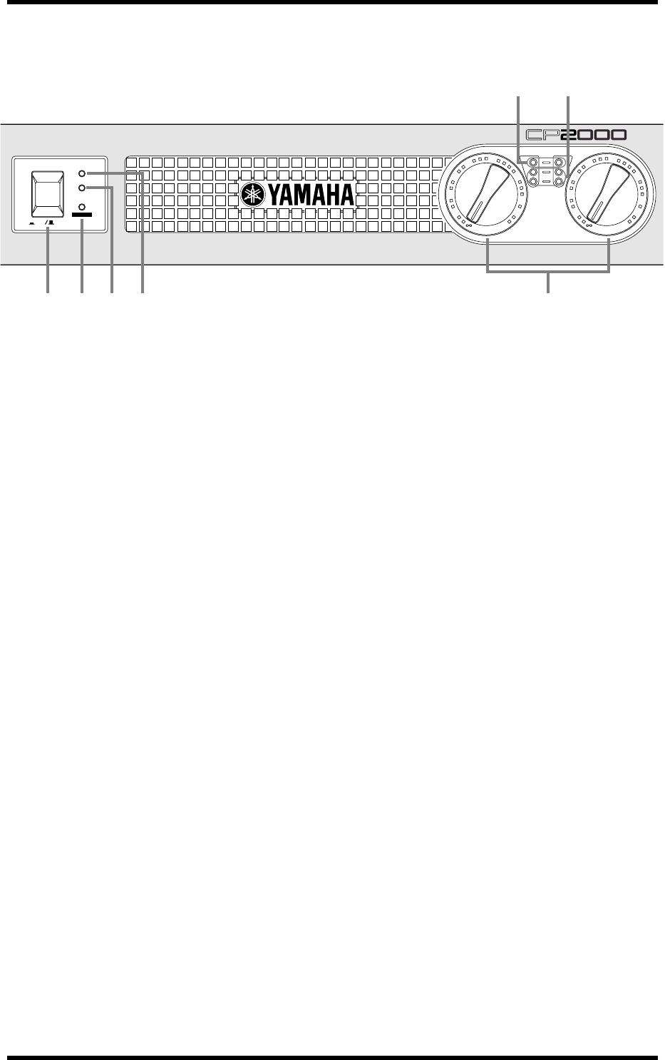
Front Panel
A
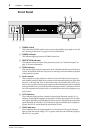
POWER switch
This is the main POWER switch. Press to turn on the amplifier; press again to turn off.
See “Turning On the Power” on page 11 for more information.
B
POWER indicator
This indicator lights up when the CP2000 is turned on.
C
PROTECTION indicator
This indicator shows the status of the protection system. See “Protection System” on
page 11 for more information.
D
TEMP indicator
This indicator lights up if the temperature of the CP2000’s heatsinks exceed 85 degrees
Celsius. Note that this indicator only serves as a warning. It does not indicate operation
of the protection system.
E
Level controls
These controls are used to adjust the volume level of each channel. Since the gain of
each amplifier channel is fixed, these controls work by attenuating the input signal from
between –
∞
dB and 0 dB. They are detented controls, which means they can be set to
any one of 31 positions. Detents protect against accidental adjustment, allow repeatable
setting, and make it easy to set both channels to the same volume. Usually these controls
are set to maximum and volume levels are controlled from the source equipment, typ-
ically a mixer.
F
CLIP indicators
These indicators light up when a channel’s output signal distortion exceeds 1% (i.e.,
clipping). Output signal clipping is usually due to excessive input signal levels. If a chan-
nel’s output signal does clip, that channel’s limiter circuit is activated to prevent further
signal distortion. It’s okay for a CLIP indicator to light occasionally, but if it lights fre-
quently, the LEVEL control should be turned down a little.
G
LEVEL indicators
These indicators show the output signal level of each channel. The green indicators
light up when the output voltage is 2 V or greater, while the yellow indicators light up
when it’s 20 V or greater.
POWER
ON OFF
TEMP
PROTECTION
POWER
POWER AMPLIFIER
–dB
LEVEL
CLIP
L
L
R
0
3
6
10
15
20
25
30 30
40
R
0
3
6
10
15
20
25
40
1
6
7
5
2 3 4