


10 Chapter 3—Using the CP2000
CP2000—Owner’s Manual
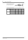
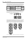
The following table shows which outputs can be used in each CP2000 mode and the
minimum speaker impedance. Note that this is the total speaker impedance that can be
connected to each channel. For example, a 2Ω minimum means that you could connect
a single 2Ω speaker, two 4Ω speakers in parallel, or four 8Ω speakers in parallel.
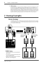
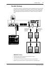
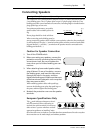
In the STEREO and PARALLEL modes, you can connect speakers to a channel’s 1/4"
phone jack and binding posts simultaneously, so long as the total impedance is not less
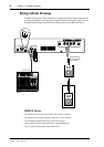
than 4Ω. In BRIDGE mode, the speakers must be connected to the binding posts
labeled “BRIDGE” and the 1/4" phone jacks cannot be used.
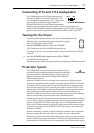
When connecting speakers, it’s important that the total impedance is not less than the
minimum specified. In STEREO and PARALLEL modes, the minimum impedance is
2Ω, and for BRIDGE mode it’s 4Ω. When speakers are connected in parallel, the
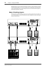
impedance is reduced, as shown in the following examples. When connecting multiple
speaker cabinets, make sure the total impedance is not less than the minimum.
See the “Hookup Examples” on page 4 for more information on connecting speakers.
Mode Item STEREO PARALLEL BRIDGE
Channel R
Phone jack (2)
2Ω min
X
Binding posts (1)
4Ω min
Channel L
Binding posts (1)
2Ω min
Phone jack (2)
X
221
CHANNEL R CHANNEL L
SPEAKERS
BRIDGE(–) (+)
1
4Ω min4Ω min
(total 2Ω min)
STEREO and PARALLEL
mode only
4Ω min4Ω min
(total 2Ω min)
8Ω
Total = 2Ω
8Ω
8Ω
8Ω
8Ω
Total = 4Ω
8Ω
4Ω
Total = 2Ω
4Ω