


Using the CP2000
7
CP2000—Owner’s Manual
3 Using the CP2000
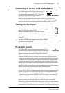
Installation
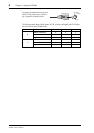
The CP2000 can be mounted in a standard rack and requires 2 rack-space units. In
addition to the front-panel rack-mounting holes, the CP2000 also features support
brackets at the rear, which offer additional support and should be fixed to the rear of
the rack. The CP2000 can also be placed horizontally on the floor or a suitable table.
The CP2000 uses a variable-speed low-noise fan to regulate the system temperature,
which draws air in from the front and expels it from the rear. For correct operation, it’s
important that the air flow at the front and rear of the CP2000 is not blocked or
restricted in any way. If the CP2000 is mounted in a portable rack with removable front
and rear covers, be sure to remove the covers before using the CP2000.
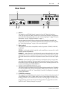
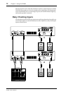
Connecting Inputs
The inputs for each CP2000 channel comprise of one 1/4" phone jack and one
XLR-3-31-type connector. Both connectors are electronically balanced, although they
can also be used with unbalanced sources. For optimum performance, use only quality
screened cables for input connections. Under no circumstances should you connect
more than one sound source to the same channel. The inputs are designed to work with
line-level sources, such as mixers, CD players, and other professional audio equipment.
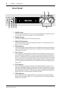
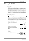
The 1/4" TRS (Tip-Ring-Sleeve) phone jacks are wired as follows: sleeve–ground,
tip–hot (+), and ring–cold (–).
TRS phone plugs should be wired as fol-
lows.
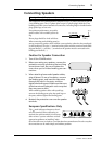
To connect an unbalanced source to an
INPUT jack, connect the ring (cold) ter-
minal to the sleeve (ground) terminal, as
shown.
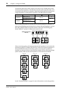
The XLR-type connectors are wired as follows: pin 1–ground, pin 2–hot (+), and pin
3–cold (–).
Male XLR plugs should be wired as fol-
lows.
Warning: Turn off all equipment before making any connections.
1/4" TRS phone plug
Tip (hot)
Ring (cold)
Sleeve (ground)
1/4" TRS phone plug
Tip (hot)
Ring (cold)
Sleeve (ground)
Male XLR plug
1 (ground)
3 (cold)
2 (hot)