


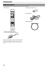
E-6
PREPARATION..................................................................
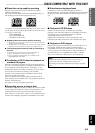
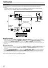
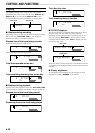
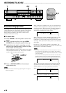
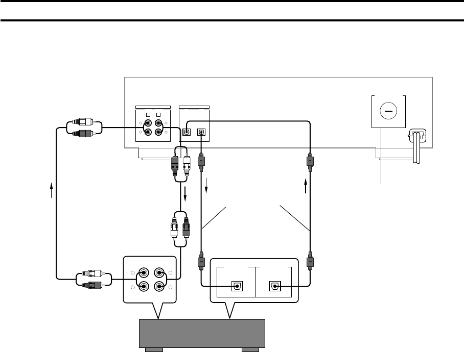
Connections
Turn off the power of this unit and the other component, and unplug them from the wall outlet before making any
connections.
• Correctly connect the input and output jacks on this unit to the input and output jacks on the other component.
• Arrow marks (→) in the illustration below indicate the direction of the audio signal.
■ Digital connections
• Remove the jack covers for DIGITAL IN OPTICAL and DIGITAL OUT OPTICAL before starting to make connections.
Using the optical fiber cable, connect the DIGITAL IN OPTICAL on this unit to the DIGITAL OUT OPTICAL on the other
component, and the DIGITAL OUT OPTICAL on this unit to the DIGITAL IN OPTICAL on the other component.
• Keep the jack covers for future use. Replace them in order to protect the digital jacks from dust when the jacks are not
being used.
■ Analog connections
• Make sure to correctly connect the L (left) and R (right) ANALOG LINE IN (REC) and ANALOG LINE OUT (PLAY) jacks
on this unit to the L (left) and R (right) ANALOG LINE OUT (REC) and ANALOG LINE IN (PLAY) jacks on the other
component.
• Connect the ANALOG LINE IN (REC) jack on this unit to the ANALOG LINE OUT (REC) jack on the other component,
and the ANALOG LINE OUT (PLAY) jack on this unit to the ANALOG LINE IN (PLAY) jack on the other component.
• The ANALOG LINE IN (REC) and ANALOG LINE OUT (PLAY) jacks on this unit are numbered 4 and 3 respectively.
Connect these jacks to the jacks with same numbers when connecting this unit with YAMAHA amplifier or receiver.
Plug in this unit to a wall outlet when all connections are complete.
ANALOG
LINE IN
REC
4
PLAY
3
LINE OUT
R
L
R
L
DIGITAL
OPTICAL
IN OUT
REC
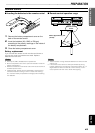
VOLTAGE SELECTOR
PLAY
OUT
IN
DIGITAL IN DIGITAL OUT
OPTICAL OPTICAL
R
L
R
L
110V
120V
220
V
240V
RCA pin cable
(included)
RCA pin cable
(included)
Optical fiber cables
(One included)
To wall outlet
Amplifier or Receiver
Voltage Selector
(General model)