


9
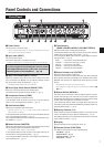
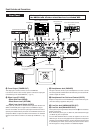
Panel Controls and Connections
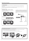
@0 Line Out Source Switch
(LINE SOURCE: THRU/PRE EQ/POST EQ)
This switch is used to select the signal that is delivered from the LINE
OUT jack.
THRU ........... Delivers the signal received via the INPUT jack without
alteration.
Select this setting when connecting to a DI (Direct In-
jection) box.
PRE EQ ....... Delivers the signal before it has been processed by the
tone controls (the Sound Type is active).
This setting can be used when separate EQ settings
are required for speaker and line outputs.
POST EQ ..... Delivers the signal after it has been processed by the
tone controls.
This setting can be used when you want the line signal
processed with the same EQ setting as the speaker.
* The FX LOOP is active on both PRE EQ and POST EQ signals.
@1 Speaker Simulator Switch (SP SIM: OFF/LINE/ON)
This switch is used to switch the Speaker Simulator circuit ON/OFF.
When the Speaker Simulator is activated, this special circuit adds the
live characteristics of a speaker to the line out signal and headphones
output. This feature is also effective when you want to produce a dis-
torted sound with the tweeter level raised.
The sound created with the Speaker Simulator is optimized to compli-
ment the selected Sound Type.
OFF .............. Deactivates the Speaker Simulator on LINE OUT,
SPEAKER, and PHONES jack signals.
LINE............. Activates the Speaker Simulator on LINE OUT, and
PHONES jack signals only.
ON................ Activates the Speaker Simulator on LINE OUT,
SPEAKER, and PHONES jack signals.
*The Speaker Simulator can only be applied to the LINE OUT jack output
when the @0 Line Out Source Switch is set to “POST EQ”.
@2 Output Limiter Switch (OUTPUT LIMITER: ON/OFF)
This switch is used to switch the Output Limiter circuit ON/OFF.
When set to the ON position, the limiter suppresses the signal if it ex-
ceeds the threshold before sending it to the SPEAKER jack and LINE
OUT jack.
OFF .............. Deactivates the Limiter on both LINE OUT and SPEAKER
jack signals.
ON................ Activates the Limiter on both LINE OUT and SPEAKER
jack signals.
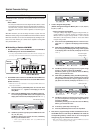
@3 MIDI OUT Jack
Connect this jack to the MIDI IN jack on an external MIDI device that
can save MIDI data (such as a MIDI data filer, etc.), and save patch data
from the BBT500 to an external device. (→ pg. 17: MIDI Bulk Out)
Also, when MIDI Merge is set ON, MIDI data received from an external
MIDI device via the MIDI IN jack is transmitted from the MIDI OUT jack
without alteration. (→ pg. 17)
@4 MIDI IN Jack
Connect this jack to the MIDI OUT jack on MIDI Foot Controller, etc., to
select patches, control volume, etc., with the MIDI Foot Controller. (→
pg. 16)
Also, patches that have been saved to an external MIDI device can be
loaded into the BBT500’s internal memory. (→ pg. 17: MIDI Bulk IN)
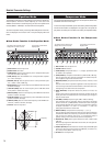
@5 Speaker Jacks (SPEAKER 1, 2 (EXT))
Two Speaker Jacks are provided for connecting speaker systems.
The amp’s internal speaker (4 Ω) is connected to the SPEAKER 1 jack.
The SPEAKER 2 (EXT) jack can be used to add an external speaker(s).
Also, if necessary, you can disconnect the internal speaker to connect 2
external speakers directly to the amp.
The two speaker jacks are connected in parallel. When external speak-
ers are used, make sure the speakers meet the following requirements.
● When using a single SPEAKER Jack (1 or 2)
Please use a system that complies with one of the following re-
quirements.
• The total impedance* of the circuit should never be less than 2Ω.
•A 2Ω speaker system must have a power handling capability of
500W or greater.
•A 4Ω speaker system must have a power handling capability of
250W or greater.
• An 8Ω speaker system must have a power handling capability of
125W or greater.
● When using both SPEAKER Jacks (1 & 2)
Please use a system that complies with one of the following re-
quirements.
• The total impedance* of the circuit should never be less than 2Ω.
•A 4Ω speaker system must have a power handling capability of
250W or greater.
• An 8Ω speaker system must have a power handling capability of
125W or greater.
To obtain optimum performance from the amplifier, we recommend con-
necting the internal speaker to the SPEAKER 2 jack, and using the
SPEAKER 1 jack to connect an external speaker (set) with a 4Ω imped-
ance and power handling capacity of 250W or greater.
* See page 10 for more information on total speaker impedance.
* For U.S. and Canadian models only
To protect against electromagnetic waves, attach the sup-
plied Clamp Filters to the cables connecting the amplifier’s
SPEAKER 1, 2 (EXT) jacks to the speakers. (→ pg. 10)
@6 Tweeter Level Control (TWEETER LEVEL)
This controls the built-in tweeter speaker’s output level (mainly high fre-
quencies above 4 kHz).
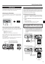
@7 Power Connector (AC IN)
Connect the supplied power cable to this terminal to supply the unit with
power from an AC power outlet.
When connecting the power cable, make sure the
amplifier’s POWER switch is turned OFF.