


15
INPUT
TUNER
OUT
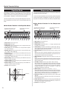
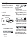
First amplifier (HPF 500Hz)
Second amplifier (LPF500Hz)
Produces
higher
frequencies
above 500Hz
Produces
low
frequencies
up to 500Hz
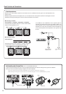
* Set the INPUT LEVEL
to its minimum level
INPUT
Bass
* Set to “h50” with
the COMP control
knob
* Set to “L50” with the
COMP control knob
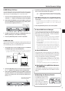
q w e
When the COMP knob is used (when
setting the crossover filter), the setting’s
value is shown in the display. Other than
that, only
utL appears on the display.
Individual MIDI
Settings
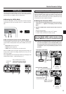
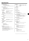
Crossover Filter
By connecting two BBT500s as shown in the illustration below, you can
create a bi-amplified system, where one amplifier is used to drive high
frequencies and a second amplifier drives low. This system uses the
amplifier’s onboard crossover filter (LPF or HPF) to determine the range
of frequencies that each amplifier will deliver.
● Setting the Crossover Filter
1 Press and hold the [FUNCTION] switch for more than three sec-
onds (until “utL” appears on the display) to enter the Utility
Mode.
2 Rotate the COMP knob to set the Crossover filter’s cutoff fre-
quency.
* Range of cutoff frequency
L10 (LPF 100Hz) to L00 (LPF 1000Hz), byP (Bypass),
h10 (HPF 100Hz) to h00 (HPF 1000Hz), 93 steps
When using a bi-amplified system, make sure
that the INPUT LEVEL control knob on the
second BBT500 is set to its minimum level.
Ex.) Operating a bi-amplified system in which the crossover fil-
ter on the first amplifier is set to h50 (HPF 500Hz) to pro-
duce high frequencies, and the crossover filter on the sec-
ond amplifier is set to L50 (LPF 500Hz) to produce low fre-
quencies.
Utility Mode
The Utility Mode provides settings for the Crossover Filter and MIDI.
These settings are saved internally when you exit the Utility Mode and
kept even when the amplifier’s power is switched OFF.
● Entering the Utility Mode
To enter the Utility Mode, from any mode press and hold the [FUNC-
TION] switch for more than 3 seconds, until “utL” appears on the dis-
play.
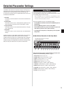
● How Knobs Function in the Utility Mode
In the Utility Mode, only the INPUT LEVEL, OUTPUT, and COMP knobs
function. All other knobs (SOUND TYPE, GAIN - TREBLE) have no func-
tion.
• INPUT LEVEL: Sets the Input Level
• OUTPUT: Sets the output level
• COMP: Sets the cut off frequency of the crossover filter
When the COMP knob is used (when setting the crossover filter), the
setting’s value is shown in the display. Other than that, only utL ap-
pears on the display.
Use the [MANUAL] switch and Memory Switches [1] through [5] to set
individual MIDI settings. (→ [MIDI Settings] pg. 16)
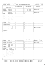
Detailed Parameter Settings