


7
Panel Controls and Connections
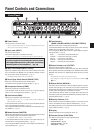
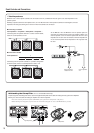
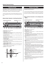
Front Panel
!0
q w e r t y u i o
!1 !2 !3
q Power Switch
This is the unit’s main power switch.
*Always set the OUTPUT volume to “0” before switching the power ON or
OFF to protect the speaker from damage.
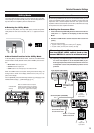
w Input Jack (INPUT)
This is the unit’s input jack.
Connect the output jack on your bass to this jack.
* Make sure that the power is switched OFF before connecting the bass.
* For U.S. and Canadian models only
To protect against electromagnetic waves, attach
the supplied Clamp Filter to the cable connecting
the bass guitar to the amplifier. (→ pg. 10)
e Input Level Volume (INPUT LEVEL)
Adjusts the amplifier’s input volume level and the volume of the bass
that is connected to the BBT500. Use the indicators located on either
side of the knob to check the signal level. (→ pg. 11)
*The INPUT LEVEL setting is not saved in memory.
r Sound Type Select Switch (SOUND TYPE)
Select one of the eleven preset sound variation types.
The indicator of the selected sound type will light. (→ pg. 11)
t Compressor Volume (COMP)
Adjusts the compressor’s compression ratio.
In the Equalizer mode, this knob is used to set the center frequency
(PEQ F) of the 1-band parametric equalizer. (→ pg. 14)
y Gain Volume (GAIN)
Adjusts the pre-amplifier’s gain volume level.
*When this knob is set to “0”, no sound will be produced although the
Master Volume is turned up.
In the Equalizer Mode, this knob is used to set the bandwidth (PEQ Q)
of the 1-band parametric equalizer. (→ pg. 14)
In the Compressor Mode, this knob is used to set the compressor thresh-
old (THRSLD). (→ pg. 14)
u Master Volume (MASTER)
Adjusts the overall volume of the sound created with the Gain and Tone
Control settings. Adjusts the preamplifier’s output level.
*The MASTER volume setting is saved in memory.
In the Equalizer Mode, this knob is used to set the Gain (PEQ G) vol-
ume level of the 1-band graphic equalizer. (→ pg. 14)
In the Compressor Mode, this knob is used to adjust the compressor’s
attack (ATTACK) time. (→ pg. 14)
i Tone Controls
(BASS, LOW MID, MIDDLE, HIGH MID, TREBLE)
Adjusts the level of their corresponding frequencies.
In the Equalizer Mode, these knobs are used to set the center frequency
(FREQ) for their corresponding tone control. (→ pg. 14)
In the Compressor Mode, these knobs are used to adjust the param-
eters given below. (→ pg. 14)
BASS ........... Compressor’s release (RELEASE) time
LOW MID ..... Compressor’s output gain (C. GAIN)
MIDDLE ....... Compressor’s knee (KNEE)
HIGH MID .... Noise gate threshold (N. GATE)
TREBLE ....... Effect loop blend level (BLEND)
o Output Volume Level (OUTPUT)
Adjusts the power amplifier’s output level.
This knob is used to set the overall volume level (the amount delivered
by the speaker) of the sound created by the pre-amplifier section’s GAIN,
MASTER, Tone Controls, etc. Adjusting this volume level has no effect
on tone.
*The OUTPUT level setting is not saved in memory.
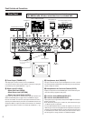
*This setting does not effect the output level (volume) of the LINE OUT (!8,
!9) jacks.
!0 Manual Switch (MANUAL)
This switch resets all parameter values (including Equalizer and Com-
pressor mode settings) to the state they were in when the power was
switched ON. All knobs function as labeled on the panel, and the setting
for each control corresponds to the position of the knob.
If you continuously hold the switch, all settings will be returned to the
state that they were in just before the [MANUAL] or Memory switch was
pressed (Undo Function). (→ pg. 13)
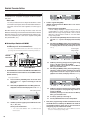
!1 Memory Switches (1-5)
These switches are used to recall data for patches (1-5) saved in the unit’s
memory. The selected memory’s (switch’s) indicator lights. (→ pg. 12)
After editing patch data, press and hold the switch for about 1 second to
save the data to memory. (→ pg. 12)
!2 Display
Displays information such as parameter values, etc.
!3 Function Switch (FUNCTION)
This switch is used to select the unit’s operating mode.
• Amp Mode (→ pg. 13)
• Equalizer Mode (→ pg. 14)
• Compressor Mode (→ pg. 14)
• Utility Mode (→ pg. 15)