


Model PA4100X Page 7
© 2003 Xantech Corporation
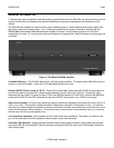
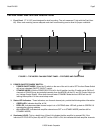
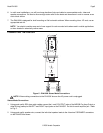
10. Grounding Screw. Provides a means for chassis connection to earth ground or to other A/V products to
aid in the reduction of system noise, etc., where needed.
11. REMOTE MASTER ON/OFF and MUTE CONTROL (CI1 & CI2). These two Stereo Mini Jack
connections allow each individual channel pair of the PA4100X to be powered ON and OFF and muted
by a control voltage ranging between 5 and 30 Volts DC (11mA @ 12 V). When connected to the C01
and C02 jacks from Zones 7 & 8 on the Xantech MRC88, this will allow remote Power ON/OFF control
directly from the MRC88 System Controller. This allows the ‘A’ & ’B’ amplifier channel pairs to be
individually controlled by Zones 7 & 8 of the MRC88. (Tip = ON/OFF Standby Control; Ring = Mute
Control; Sleeve = gnd).
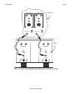
12. 3-Conductor AC Line Cord Receptacle. Standard IEC male receptacle for plug-in of a 3-conductor
power line cord. Depending on the application, plug the line cord into a switched or un-switched 120V 60
Hz AC outlet (or 240 VAC 50 Hz on the 240 V version).
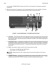
13. Rear Panel POWER LED. This LED indicates the AC power ON/OFF condition of the entire PA4100X,
regardless of the Standby state. If the Front Power Switch is in the ON (IN) position and the unit is
connected to an adequate AC Power source, this LED should be illuminated whether the front STATUS
LED’s are ON or OFF.
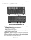
14. REMOTE/LOCAL CI Control Switch: When set to the ON (UP) position, Remote Standby ON/OFF
control of the amplifier will be determined by the Voltage state applied to the CI1 and CI2 control inputs
(Item #11) (Front Power Switch – Item #2 must be in the IN position). When set to the OFF (DOWN)
position, the amplifier will operate according to the Front Power Switch regardless of voltages applied to
the CI1 and CI2 inputs.
NOTE: With the CI switch in the ON (UP) position, a control signal MUST be used on the CI1 and CI2
inputs otherwise the PA4100X will remain in STANDBY MODE.