


Page 10 Model PA4100X
© 2003 Xantech Corporation
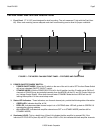
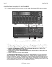
3. The PA4100X is 4-Ohm safe in Stereo Mode. Make sure the impedance presented to the speaker terminals by
the speakers (or any combination of speakers) is 4-Ohms minimum.
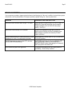
5. Be sure to observe correct polarity by connecting the "+" and "–" terminal from each channel on the PA4100X to
the corresponding "+" and "–" terminals on each speaker. This will ensure correct "phasing" - see Fig. 5 and
Speaker Phasing below. Since the connectors are removable, you may unplug them for ease of lead assembly.
6. As a rule of thumb, use 18 gauge speaker wire for speaker runs up to 30' (9m), 16 gauge up to 70' (21m), and 14
gauge up to 150' (39m). The 4-terminal connectors accept wire sizes up to 12-gauge max.
7. Strip the insulation back about 1/4" (6mm) and twist the strands on each lead to prevent fraying.
CAUTION: After lead ends are inserted and the screws tightened down, be sure there are no free strands that
could cause shorting!
Speaker Phasing
To obtain stable imaging and full bass response, it is imperative that stereo speakers be connected "in phase" with
each other. You can verify this as follows:
a) If the "+" (positive) and "–" (negative) terminals on your speakers are correctly marked, and visible, and you have
wired the system as shown in Figs. 5, then the system will be "in phase". No further action is required. Most
manufacturers identify the positive terminal with a red binding post, a "+" sign, or a red dot.
b) If you are unsure of the markings, you can verify the phasing. Using a mono sound source, such as AM radio,
alternately reverse the leads to one of the speakers. Pick the connection that delivers a solid center image
between the speakers as well as best bass response.
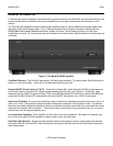
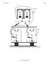
Connecting the REMOTE MASTER ON/OFF MUTE CONTROL
As mentioned under "PA4100X PANEL AND FEATURE DESCRIPTIONS", the REMOTE MASTER ON/OFF
CONTROL inputs (CI1 & CI2) will allow the power to the PA4100X to be turned ON, OFF, and MUTED by remotely
applied DC Voltages. Fig. 7 illustrates how a PA4100X can be switched ON and OFF via the MRC88 Zone 7 & 8
Control Outputs (CO1 and CO2) or other control source.
NOTE: To enable this feature, be sure the CI Switch (Item #14) is in the ON (UP) position.
On/Off Standby Control:
Whenever a 5 to 30v dc voltage is applied to the TIP of the 3.5mm Stereo jack, the associated Amplifier channel will
be activated (Powered ON). When the signal applied to the TIP approaches GND, it will put the associated Amplifier
channel in STANDBY Mode. If both Amplifier channels are in STANDBY MODE the Amplifier will enter a “low power”
STANDBY mode (Illuminated LOGO will remain ON).
Mute Control:
Whenever a 5 to 30v dc voltage is applied to the RING of the 3.5mm Stereo jack, the associated Amplifier channels
signal output will be MUTED. When the signal applied to the RING approaches GND it will UN-MUTE the associated
Amplifier channel and the audio signal will be returned to its previous level.
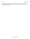
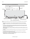
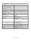
Tip:12vDC = AMP ON
Ring:12v DC = AMP MUTED
Sleeve=GND
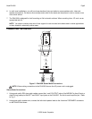
Insulators
3.5mm Mini Plug
(3-Conductor)
Figure 6: CI Control Jack Pin Out Config