Model PA4100X Page 5
© 2003 Xantech Corporation
PA4100X PANEL AND FEATURE DESCRIPTIONS
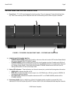
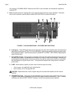
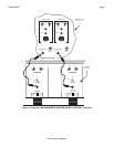
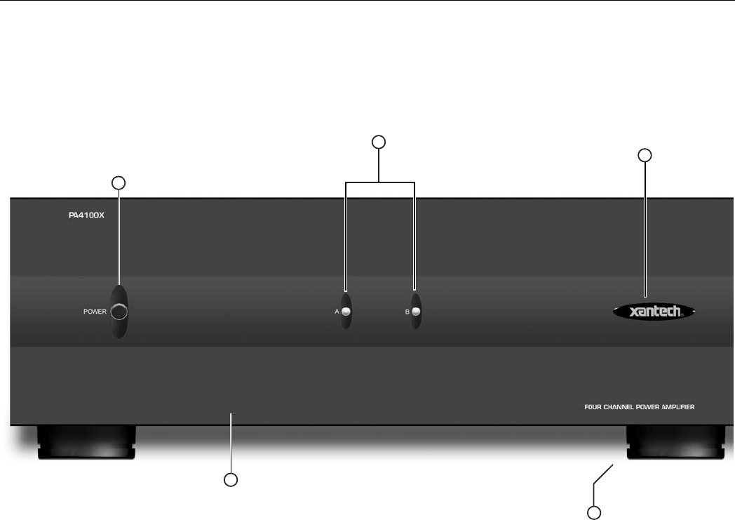
1. Front Panel. 17" X 5.25” panel designed for shelf mounting. The unit measures 6” high with the Feet (Item
#5). When rack mounting use an adequate rack shelf mount making sure to allow for proper ventilation.
5
4
3
1
2
FIGURE 2 – THE MODEL PA4100X FRONT PANEL – FEATURES AND FUNCTIONS
2. POWER ON/OFF/STANDBY SWITCH:
POWER ON/OFF MODE: When the CI switch on the rear of the unit is set to OFF the front Power Switch
will act as a standard ON/OFF (IN/OUT) control.
STANDBY MODE: With the POWER SWITCH left in the IN position (and the CI switch set to ON) the 2
channels of PA4100X may be controlled remotely from the MRC88 via the CI1 and CI2 Control Inputs (or
any Voltage Control Signal). When both channels enter STANDBY Mode the front LEDS will turn off
leaving the amplifier in a low current sleep mode.
3. Status LED Indicators. These indicators, one for each channel pair, provide the following status information:
GREEN LED: Indicates Amplifier is ON
RED LED: Indicates associated channel output is in a CLIPPING state. LED will go back to GREEN 5-6
seconds after clipping subsides.
ALL LED’s OFF: Indicates both amplifier channels are OFF or in STANBY MODE (see Item #4 for
STANDBY MODE)
4. Illuminated LOGO: This is a backlit logo. When lit it indicates that the amplifier is powered ON. If the
individual STATUS LED’s (Item #3) are OFF but the LOGO is ON, this indicates that both amplifier channels


