


SoundPlus
®
Value Courtroom System • Model WIR SYS 2
SoundPlus
®
Value Courtroom System • Model WIR SYS 2
D
D
NOTE: SPECIFICATIONS SUBJECT TO CHANGE WITHOUT NOTICE!
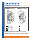
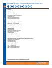
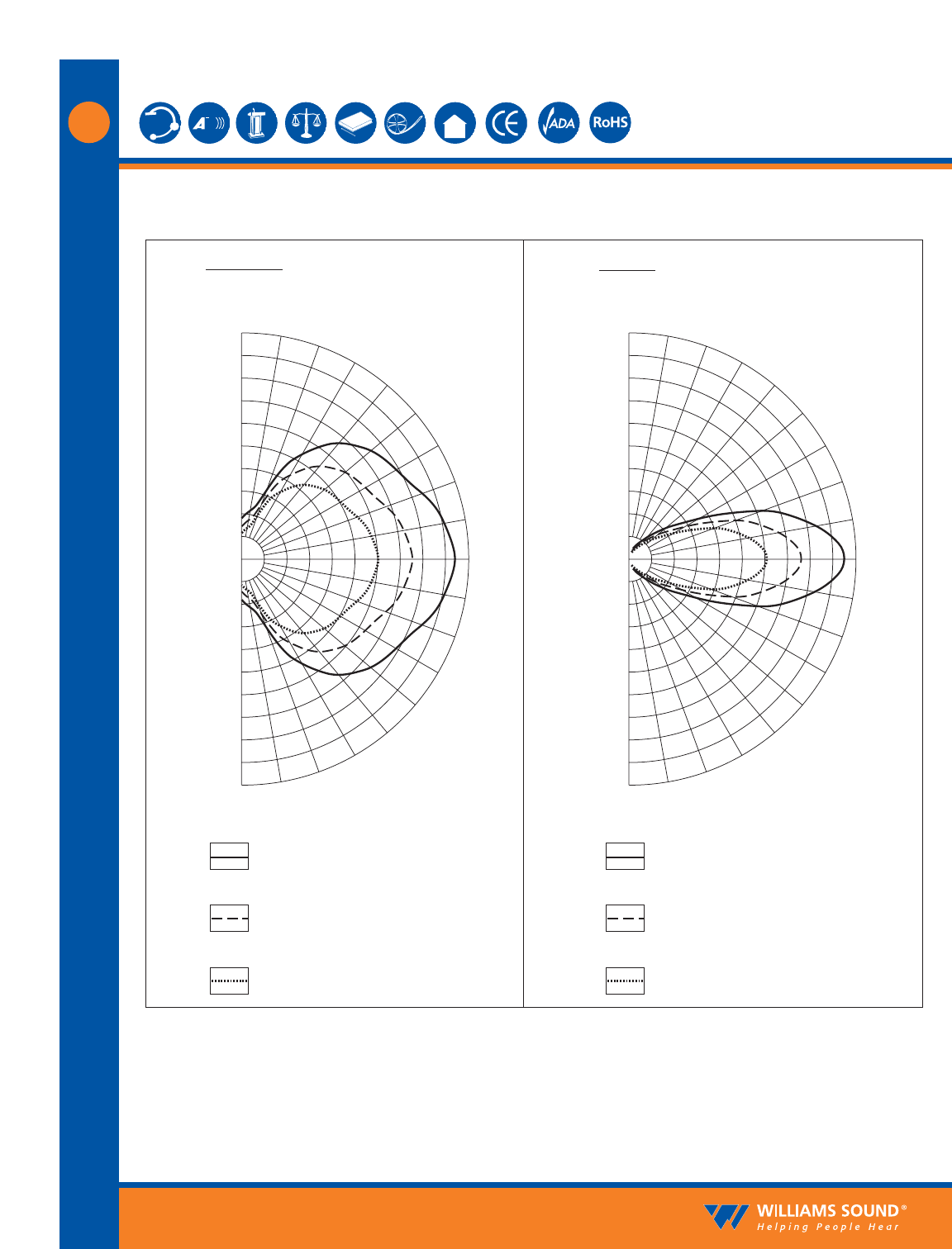
Maximum Range When Using the RX22-4 Infrared Receiver
20
6
12
18
24
30
36
42
48
54
60
40
60
80
100
120
140
160
180
200
FEET
METERS
– 90
– 80
– 70
– 60
– 50
– 40
– 30
– 20
– 10
0
10
20
30
40
50
60
70
80
90
1 Channel, 1 nW/sq cm
(Approx. 28000 sq ft, 2600 sq m)
2 Channel, 1 nW/sq cm per channel
(Approx. 18000 sq ft, 1700 sq m)
4 Channel, 1 nW/sq cm per channel
(Approx. 11000 sq ft, 1000 sq m)
1 Channel, 1 nW/sq cm
2 Channels, 1 nW/sq cm per channel
4 Channels, 1 nW/sq cm per channel
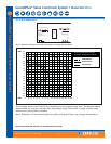
HORIZONTAL RADIATION POLAR PATTERNS
DISTANCE FROM EMITTER TO 1 nW/sq cm CONTOUR
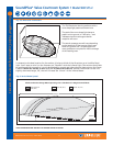
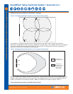
VERTICAL RADIATION POLAR PATTERNS
DISTANCE FROM EMITTER TO 1 nW/sq cm CONTOUR
20
6
12
18
24
30
36
42
48
54
60
40
60
80
100
120
140
160
180
200
FEET
METERS
– 90
– 80
– 70
– 60
– 50
– 40
– 30
– 20
– 10
0
10
20
30
40
50
60
70
80
90
Reflections of the infrared light from walls, ceilings, and floors may change these patterns.
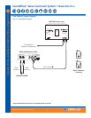
Important: Remember to point the emitter towards the listening audience!
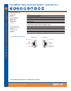
If you’re not getting sufficient coverage with a single, properly installed TX9 Emitter, you may need
to add additional WIR TX9 Emitters to achieve full coverage of your listening area. Figures 8a and
8b illustrate how multiple emitters can be used for large room installations.
Fig. 7: Horizontal and Vertical Radiation Polar Plots
©2006, Williams Sound Corp. MCAT 028D
5