


SoundPlus
®
Value Courtroom System • Model WIR SYS 2
SoundPlus
®
Value Courtroom System • Model WIR SYS 2
D
D
NOTE: SPECIFICATIONS SUBJECT TO CHANGE WITHOUT NOTICE!
Bid Specs
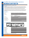
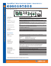
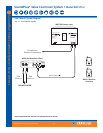
Modulator, Model MOD 232
The infrared system shall consist of separate modulator and emitter units, with portable receivers. The modulator unit
shall be a half-rack style, metal enclosure. A rack panel shall be available to mount one or two modulator units within a
single EIA rack space. An adjustable floor stand and mounting bracket shall be available to mount the modulator and
emitter together for portable operation.
The modulator shall provide two channels of selectable FM carrier signals; 2.3/2.8/3.3/3.8 MHz, so that a single modulator
can be used to simultaneously transmit up to two channels, and two modulators can be ganged together to transmit up
to four channels simultaneously. The carrier signals shall use 50 kHz deviation and 50 µS pre-emphasis. The carrier signals
(baseband) shall be transmitted to one or more emitters by 50 ohm RG58 coaxial cable with BNC-type connectors. A
BNC–type baseband input jack and baseband output jack shall be provided on the modulator. The modulator shall be
powered by an external 24 VAC, 10 VA, 50-60 Hz power supply, connected via a three-pin Molex power connector.
It shall have a rocker-type power switch, power LED indicator, four carrier indicator LEDs and two bar graph-type LED
audio indicators. The modulator shall have a modulated IR LED on the front panel for testing purposes, and a head-
phone jack that accommodates mono and stereo 1/4" headphones, and channel monitoring switch. The modulator shall
have two rotary audio input level controls, and a screwdriver adjustable control for varying the input compression from
1:1 to 4:1. The modulator shall have two timers that automatically shut off the carriers when there is no audio signal
present for 15 minutes. The modulator shall have two combination input jacks that accept 3-pin XLR plugs for balanced
microphone input or 1/4" TRS plugs for balanced or unbalanced line-level inputs. The XLR inputs shall be low impedance,
accept signal levels from 100 µV to 90 mV and supply 15 V simplex power per DIN45596. The TRS jacks shall accept bal-
anced or unbalanced audio signal levels from 21 mV to 10 V. The modulator shall have CE, FCC, RoHS, and WEEE
approval and carry a five-year parts and labor warranty.
The modulator shall be the Williams Sound Corp. model MOD 232.
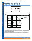
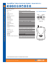
Emitter, Model TX9
The emitter shall be contained in a metal enclosure with a shatter-resistant lens. The emitter shall include an omni-direc-
tional mounting bracket for permanent installation and a bracket shall be available for mounting on a floor stand for
portable installations. Each emitter shall be powered by a 24 VAC, 50 VA, 50-60 Hz power supply. The power connector
shall be a 3-pin Molex-type. The emitter shall have a BNC-type 50 ohm baseband input and a BNC-type baseband 50 ohm
output jack. The emitter shall have a repeater circuit to allow multiple numbers of emitters to operate from the base-
band signal. The emitter shall have a visible LED indicator for power and for baseband signal. Carrier frequency is 50KHz
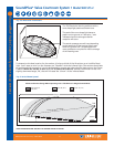
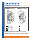
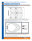
to 8 MHz. The emitter shall shut off when the baseband signal is not present. The emitter shall provide an effective cov-
erage area of 28,000 sq ft (2,600 sq m) in single channel mode and 18,000 sq ft (1,700 sq m) in two channel mode when
using the RX22-4 receiver. The emitter shall be convection-cooled, without fans. The emitter shall have CE, FCC, RoHS,
and WEEE approval and carry a five-year warranty on parts and labor.
The emitter shall be Williams Sound Corp. model WIR TX9.
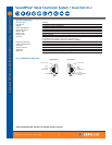
WIR RX14-2 Receiver
The receiver shall be a headset style with IR detectors positioned on top of each individual earphone. The receiver
shall operate on 2.3 MHz or 2.8 MHz frequency. The receiver shall have an individual rotary-type volume control on
each individual earphone and a on/off selection switch on the right earphone. The receiver shall have a push button
frequency selector to choose between 2.3 MHz or 2.8 MHz operation. The receiver shall provide 118 dB SSPL90 out-
put, +/- 1 dB, and a signal-to-noise ratio of 58 dB. The receiver shall operate up to 50 hours when using AAA alka-
line non-rechargeable batteries and 8 hours per charge when using AAA NiMH rechargeable batteries. The receiver
shall be encased in a black, plastic case. The receiver shall operate up to 3,500 ft
2
(325 m
2
) when using a single WIR
TX9 Emitter. The receiver shall have CE, RoHS, and WEEE approval and be covered by a one-year parts and labor war-
ranty, not including batteries or accessories.
The receiver shall be the Williams Sound Corp. model WIR RX14-2.
©2006, Williams Sound Corp. MCAT 028D
10