


SoundPlus
®
Value Courtroom System • Model WIR SYS 2
SoundPlus
®
Value Courtroom System • Model WIR SYS 2
D
D
NOTE: SPECIFICATIONS SUBJECT TO CHANGE WITHOUT NOTICE!
©2006, Williams Sound Corp. MCAT 028D
4
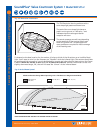
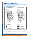
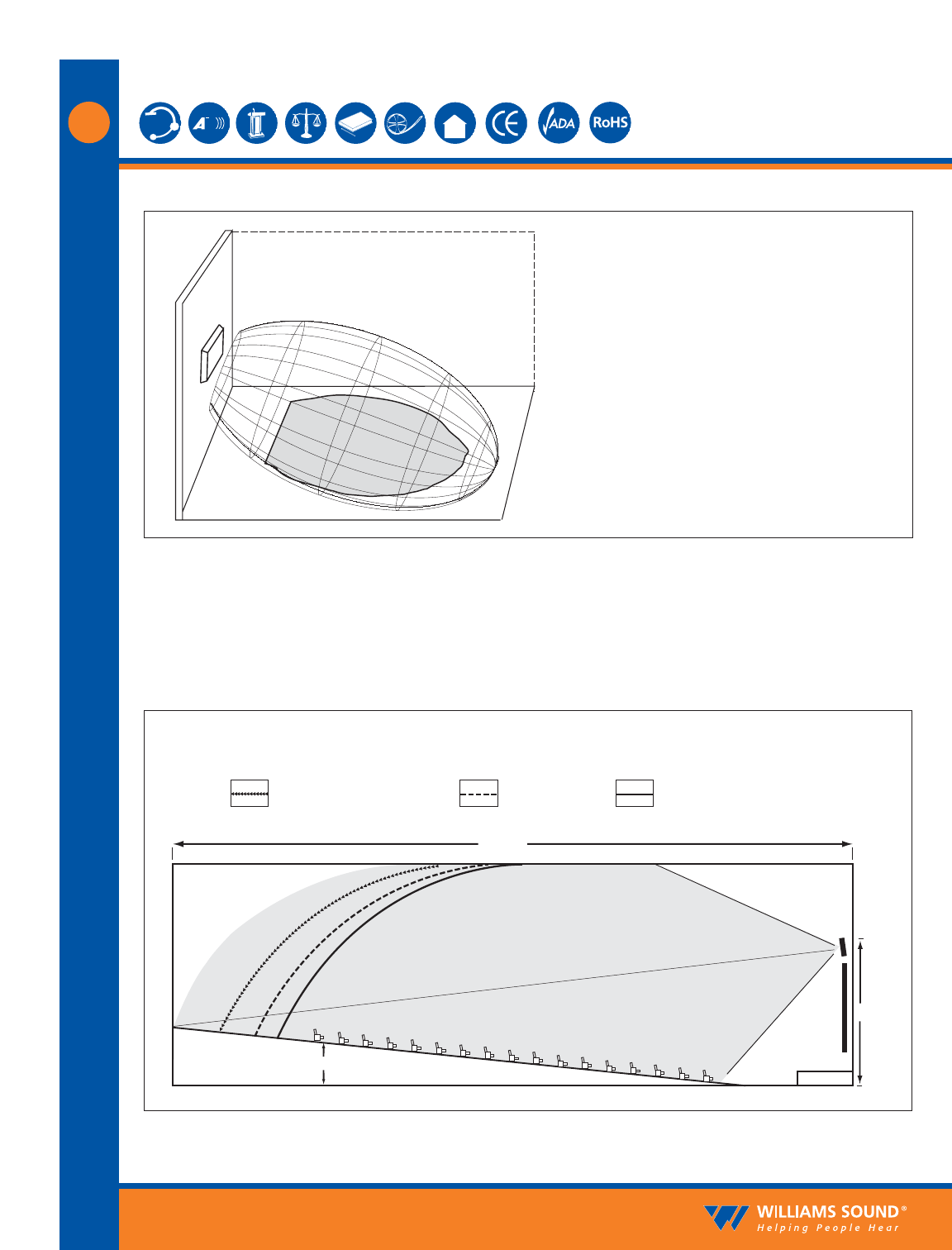
The TX9 floods the listening audience with a
cone shape light pattern as shown here.
The path of the cone shape light leaves a
pattern on the ground, or "foot print, " and
indicates where the strongest receiver
reception will occur.
The actual coverage area will vary depending
on the sensitivity of the receiver being used.
Refer to Figures 4 and 7 to determine how
many emitters are required for 100% coverage
of the listening area.
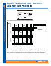
Minimum Receiver Range When Operating with a TX9 Emitter in Single Channel Mode
RX22-4 Receiver:
150' (45 m)
RX14-2: 80' (24 m) RX16: 70' (21 m)
SCREEN
30'
STAGE
6'
Center Of Emitter Beam
TX9
(Range)
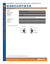
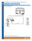
To determine the best location for the emitter, it helps to think of the IR emitter as an invisible flood-
light. You’ll want to aim it so the listeners are “flooded” with the infrared light. The emitter should also
be positioned high enough so it won’t be blocked by people and other physical obstructions. See Figure
6 below. Mount the emitter at least 2 ft. (.61 m) above the audience. Position the emitter to face in a
slightly downward angle, 20°, that will increase the “throw” of the infrared beam.
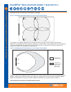
Fig. 5: 3-Dimension Foot Pattern
Fig. 6: Vertical Beam Spread