


SoundPlus
®
Value Courtroom System • Model WIR SYS 2
SoundPlus
®
Value Courtroom System • Model WIR SYS 2
D
D
NOTE: SPECIFICATIONS SUBJECT TO CHANGE WITHOUT NOTICE!
©2006, Williams Sound Corp. MCAT 028D
3
Power On Baseband On
Multi-Channel Infrared Transmitter
Made in U.S.A.
24 VACNC
CAUTION
RISK OF ELECTRIC SHOCK
DO NOT OPEN
WARNING: TO REDUCE THE RISK OF FIRE OR
ELECTRIC SHOCK DO NOT EXPOSE THIS
EQUIPMENT TO RAIN OR MOISTURE.
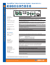
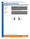
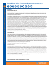
Power In:
24VAC
50-60Hz
35VA
Power Supply Wiring:
Baseband Signal Wiring:
Baseband Signal Wiring:
Note: It is normal for this unit to feel warm while it is in operation.
Plug
Use NEC, Class 2 Wiring, 18 ga. minimum,
200 ft. (70m) maximum length (18 ga.)
Use 50 Ohm Coaxial Cable (RG58)
Use RG58 Coax,1000 ft. (350m) max. length
www.williamssound.com
InOut Out
50 Ohms
Baseband
(Modulation)
~
Mounting
Bracket
RoHS
Class 1
LED Product
Williams Sound Corp., Minneapolis, Minnesota, USA
Patent Pending
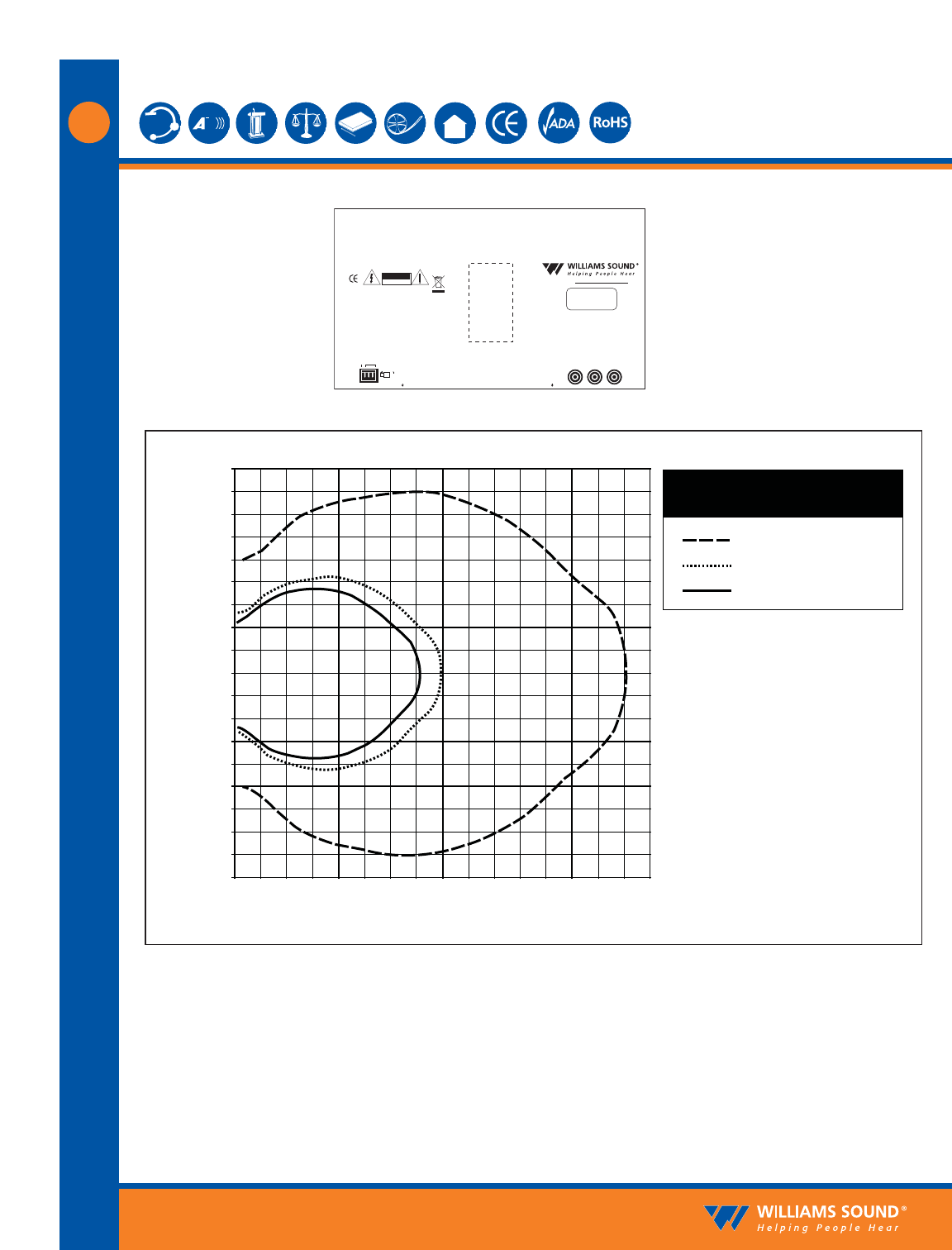
Fig. 3: WIR TX9 Rear Panel
90
Feet
Feet
90 100 110 120 130 140 150 160
80
80
70
70
60
60
50
50
40
40
30
30
20
20
10
10
0
0
-10
-20
-30
-40
-50
-60
-70
-80
-90
RX22-4 Receiver
Receiver Coverage Area with TX9
Transmitter in Single Channel Mode
RX16 Receiver
RX14-2 Receiver
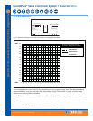
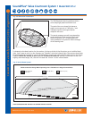
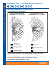
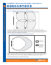
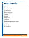
Fig. 4: Receiver Coverage Area with TX9 Emitter in Single Channel Mode
The coverage area for the TX9 will vary depending on the receiver being used. The diagram above
demonstrates the receiver coverage when operating a single TX9 emitter in single channel mode.
Patterns are direct radiation patterns.
Note: Reflections of the infrared light from walls, ceilings and floors may change these patterns.
RX22-4
RX14-2
RX16