


Page 8
DVR395/DVR396-002 Page 8 of 30
LIST OF ILLUSTRATIONS
Figure 1. Ferrite Bead Installation For DVR396 ......................................................................... 11
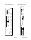
Figure 2. DVR395 Rear Panel ..................................................................................................... 13
Figure 3. DVR396 Rear Panel ..................................................................................................... 13
Figure 4. DVR395 Front Panel .................................................................................................... 18
Figure 5. DVR396 Front Panel .................................................................................................... 18
Figure 6. Welcome Banner .......................................................................................................... 21
Figure 7. Failure Banner .............................................................................................................. 21
LIST OF TABLES
Table 1. Equipment Specifications .............................................................................................. 10
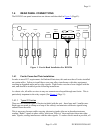
Table 2. DVR395/DVR396 Interconnect Descriptions .............................................................. 14
Table 3. DVR395 Serial Cables To Terminal or Printer ............................................................. 15
Table 4. Control DIP Switch Functions....................................................................................... 17
Table 5. Front Panel Controls and Indicator................................................................................ 19
Table 6. LED Indications............................................................................................................. 20
Table 7. SELECT And ENTER Key Functions........................................................................... 23
LIST OF CAUTIONS & WARNINGS
Warning Radio Interference ................................................................................................... 9
Caution F Connector Loading ............................................................................................... 14
Caution RJ-12 Connection .................................................................................................... 15