


Page 15
Page 15 of 30 DVR395/DVR396-002
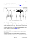
VIDEO CONNECTIONS
Composite: connect the composite video output to the desired unit using a standard
phono plug cable. The equipment it is connected to MUST have a 75-ohm termination.
S-video: connect the S-video output to the desired unit using a standard S-video mini-
DIN connector.
AUDIO CONNECTIONS
Using standard shielded audio cable with phono plugs, connect the stereo audio output to
the desired unit or equipment.
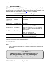
Serial Port
Using a cable terminated in an RJ-12 connector at one end and a DB9/DB25 at the other,
connect the serial port to a terminal, printer, modem, or COMPEL control system.
A Null modem cable or adapter is required for use with a modem. Defaults are
19.2KBps, N, 8, in terminal mode.
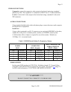
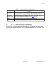
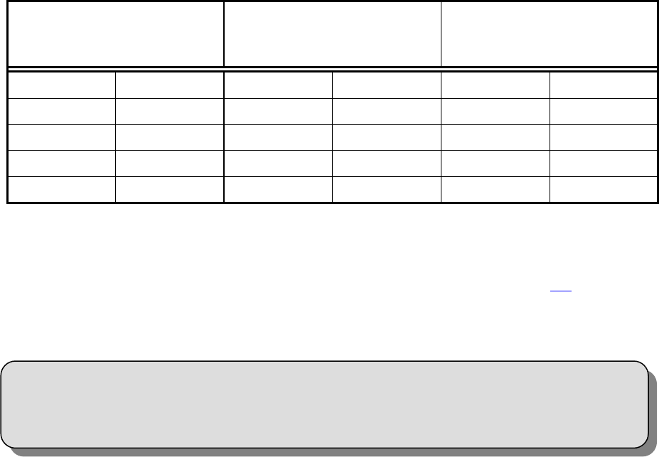
Table 3. DVR395 Serial Cables To Terminal or Printer
DVR395
RJ-12
COMPUTER
DB-9 (Female)
ASCII TERMINAL OR
SERIAL PRINTER
DB-25 (Male)
PIN SIGNAL PIN SIGNAL PIN SIGNAL
2 TX DATA 2 RX DATA 3 RX DATA
3 RX DATA 3 TX DATA 2 TX DATA
5 GROUND 5 GROUND 7 GROUND
6 RI 9 RI 22 RI
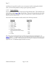
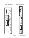
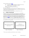
MODE SWITCH
Set the control DIP switches for NTSC/PAL, Modulator channel 2/3, Normal Video,
Color Bars, and LNB ON/OFF as required for your system. See Section 2.2
(Page 17)
for DIP switch information. FUNCTIONS ARE MODEL SPECIFIC.
* * * CAUTION * * *
DO NOT CONNECT RJ-12 DIRECTLY TO PHONE LINE.