


Waves LinMB software guide page 14 of 28
D
ISPLAYS
T
HE
M
ULTI
B
AND GRAPH
:
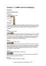
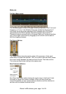
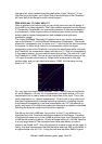
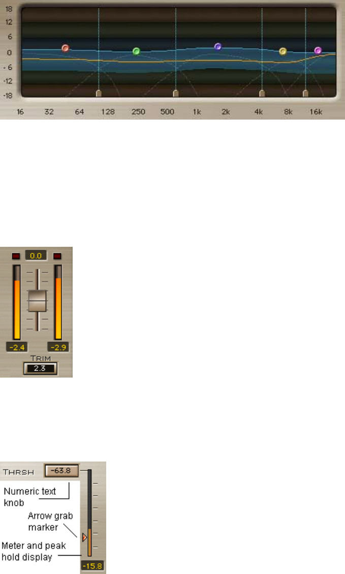
The MultiBand graph is like an EQ graph showing Amplitude in the Y-axis and
Frequency in X-axis. In the Middle of the graph resides the DynamicLine
that shows the per band gain adjustment as it happens within the Range,
represented by the Bluish highlight. Beneath the graph there are the 4
Crossover frequency markers and on the graph there are 5 markers that allow
you to set the gain of the band by dragging up and or down and the band’s
width by dragging sideways.
T
HE
O
UTPUT
M
ETERS
:
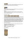
The Output meters show the master output of the processor. Under each
meter there is a peak hold indicator. The Trim control under the meters shows
the current margin between the peak and the full scale. The holds and the
Trim value are reset when clicking in the meters area.
B
AND
T
HRESHOLD
M
ETERS
:
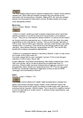
Each Band has its own meter showing the input energy in that band. Under
the meter is a peak hold numeric indicator. When you want to set your
nominal thresholds you can use the peak as reference and then continue to
set them with the master threshold control.