


77
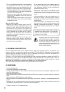
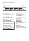
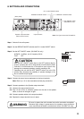
[Rear]
DA-550F
6
7
9
12
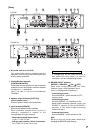
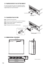
DA-500F-HL
6
7
12 13
98
8 99
1110 10
1110 10
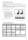
6. AC power cord (2 m or 6.56 ft)
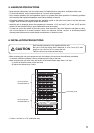
The socket-outlet shall be installed near the
equipment and the plug (disconnecting device)
shall be easily accessible.
7. Control/Monitor terminals
[CONTROL/MONITOR]
Connecting external equipment to these terminals
makes the control and monitor functions available
for channels 1 – 4 individually.
(See p.16; How to Use the Control/Monitor
Terminals.)
8. Speaker output terminals [OUTPUTS]
(with a terminal cover )
Connect speaker cables to these terminals.
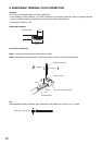
9. Input terminals [INPUTS]
Electronically-balanced input terminals.
Each removable terminal block (3 pins) is
internally connected in parallel to the
corresponding XLR type connector.
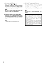
• Removable terminal block (3 pins)
H: Hot, C: Cold, E: Earth
•
XLR type male connector (XLR-3-31 equivalent)
Pin 1: Earth, Pin 2: Hot, Pin 3: Cold
If a straight plug hits the rack's rear cover or
wall behind the rack when it is used for
connection, use the L-shaped plug instead.
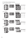
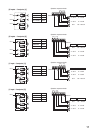
10. BRIDGE ON/OFF switches
[BRIDGE 1, BRIDGE 2, ON / OFF]
Used when bridge-connecting the unit's
Channels 1 and 2, and Channels 3 and 4.
(See p. 9; Settings and Connections.)
• 4-channel input mode
Set both BRIDGE 1 and 2 switches to OFF.
(factory-preset)
• 3-channel input mode
Set either BRIDGE 1 or 2 switches to ON.
When bridge-connecting Channels 1 and 2, set
BRIDGE 1 switches to ON, and BRIDGE 2
switches to ON when bridge-connecting
Channels 3 and 4.
• 2-channel input mode
Set both BRIDGE 1 and 2 switches to ON.
Note
Be sure to first turn off the power switch when
changing the BRIDGE switch settings.
Caution when using an XLR type plug