


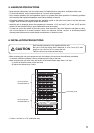
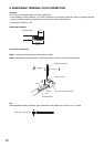
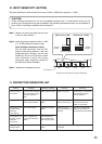

16. HOW TO USE THE CONTROL/MONITOR TERMINALS
The Control/Monitor terminals on the rear panel permit power ON/OFF control of the individual channels and
monitoring for the power ON/OFF status and protection status on each channel, and fan operation status.
Prepare the control panel and status monitor display panel separately referring to the descriptions below.
Note
All terminals are electrically isolated from the unit body with the photocouplers.
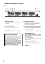
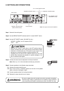
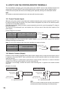
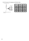
16.1. Control Terminal (Input)
While the unit's power switch is turned ON, each individual channel's power can be turned ON and OFF from
the distant location using this terminal. The power indicator extinguishes only when the all channels' powers
are turned off, but otherwise remains lit.
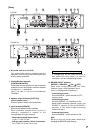
Using the power supply, which you need to prepare separately, perform the control by applying DC voltage to
the control terminal.
This terminal is a photocoupler input, and requires max. 8 mA per control. Note the power capacity of the
power supply.
Control voltages are as follows.
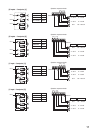
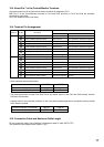
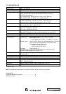
16.2. Monitor Terminal (Output)
Indicators on the externally-connected device (status monitor display panel) or relays can be turned on and off
in response to the power ON/OFF status, protection status, and fan operation status from the distant location
using this terminal.
This monitor terminal is a photocoupler open-collector output terminal. Note that it is rated at withstand
voltages of 30 V DC and control current of 12 mA or less when ON.
At the time of circuit design, consider the control current assuming that 1 V appears at the monitor terminal
when ON.
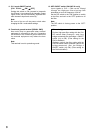
[Example of a circuit]
Control voltage (Vin) Power ON/OFF status on each channel
0 – 3 V DC ON
9 – 14 V DC OFF
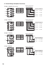
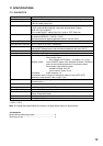
Control voltage (Vin) R1 resistance value (rated power)
14 V to under 20 V DC 1 kΩ (0.1 W or more)
20 V to under 30 V DC 3.3 kΩ (0.25 W or more)
30 V to under 50 V DC 5.6 kΩ (0.5 W or more)
When controlling the control terminal with a power supply of 14 V DC or more, connect the specified
resistance referring to the table below.
Note: The use of the resistance other than those specified may cause unit failure.
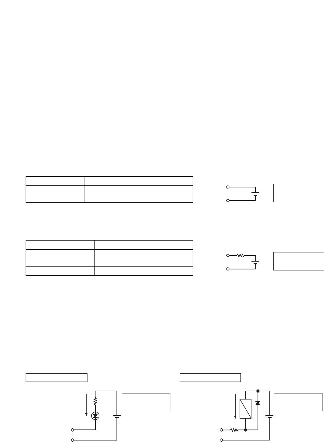
Note
Be sure to connect a diode across the relay in the direction
as shown above when connecting to the external relay.
Terminal pin No.
Pin 1 or 4
Vin
Pin 7
External DC power
(Max. 14 V DC)
Terminal pin No.
Pin 1 or 4
Pin 7
Vin
R1
External DC power
(Max. 50 V DC)
Terminal pin No.
When an LED is used
Pin 2, 3, 5, 6, or 8
Pin 7
Control current:
12 mA or less
Control current:
12 mA or less
External DC power
(Max. 30 V DC)
External DC power
(Max. 30 V DC)
Terminal pin No.
When a relay is used
Pin 2, 3, 5, 6, or 8
Pin 7
16