13
11. PROTECTION OPERATION LIST
Failure Protection Operation Indicator Remedy Recovery
Overcurrent due
to overload
Current limiter activated
when impedance drops
below the specified
value.
Peak indicator lights. Remove overload. Connecting a correct load
automatically restores
normal operation.
Short circuit Current limiter activated.
Load is disconnected.
Protection indicator
lights.
Check speakers and
lines for short circuit.
Turn off the power switch.
Correct the load, then
switch on the power.
Temperature rise
at power amp.
heat sink
(over 100°C)
Load disconnected. Protection indicator
lights.
Temperature rise
at power supply
heat sink
(over 80°C)
Built-in amplifier unit
that caused the failure
halted.
Four indicators of
the corresponding
channel extinguish.
Check the unit for
correct ventilation and
overload.
Operation automatically
returns to normal when
the temperature decreases.
Abnormal DC
voltage output
Load disconnected. Protection indicator
lights.
Contact the TOA dealer where the unit was
purchased.
10. INPUT SENSITIVITY SETTING
The input sensitivity for each channel can be set to either +4 dB (factory preset) or –10 dB.
These servicing instructions are for use by qualified personnel only. To avoid electric shock, do not
perform any servicing other than that contained in the operating instructions unless you are qualified to
do so. Refer all servicing to qualified service personnel.
CAUTION
Step 1. Unscrew 9 screws securing the top cover
of the unit, then detach it.
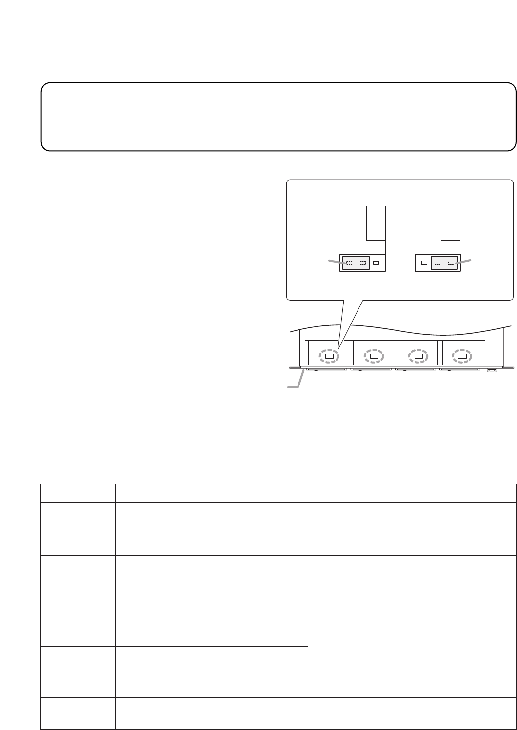
Step 2. Insert the jumper socket into either "+4 dB"
or "–10 dB" position as shown at right.
When a bridge connection is made;
Set the input sensitivity with the CH1
jumper socket when Channels 1 and 2 are
bridge-connected. Similarly, set the input
sensitivity with the CH3 jumper socket
when Channels 3 and 4 are bridge-
connected. (Input sensitivity settings for
the CH2 and CH4 are disabled.)
Step 3. Replace the detached top cover.
–10 dB/+4 dB
Input
Sensitivity
Input
Sensitivity
–10 dB/+4 dB
[When set to +4 dB] [When set to –10 dB]
Jumper
socket
Jumper
socket
(Factory-preset)
Viewed from top with the top cover detached.
Front panel
CH 1 CH 2 CH 3 CH 4


