


TORO GM 345 / 325-D Electrical Systems
Notes
_______________________________________________________________________________________________________________
_______________________________________________________________________________________________________________
_______________________________________________________________________________________________________________
_______________________________________________________________________________________________________________
_______________________________________________________________________________________________________________
_______________________________________________________________________________________________________________
_______________________________________________________________________________________________________________
_______________________________________________________________________________________________________________
_______________________________________________________________________________________________________________
57
Electrical System
(GM 345 / 325-D)
The electrical system on the 300 Series Goundsmaster can be broken into the following circuits:
1. Starting/Charging.
2. Safety Interlock.
3. Gauges and warning.
4. Engine.
With a basic understanding of these circuits we can troubleshoot a variety of electrical problems.
System Operation
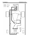
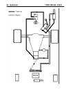
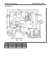
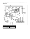
Start Circuit. (GM 345 Shown, 325-D similar)
1. Power from the battery flows to the (-) terminal of the ammeter.
2. The power flows from the (+) terminal of the ammeter to the ignition switch, terminal (X).
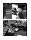
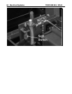
3. The power splits and flows to the seat switch.
4. The power splits again and flows to the neutral switch and PTO switch.
5. When both switches are closed the power can flow to the (B) terminal of the ignition switch.
6. When the switch is turned to the start position power flows from the (B) terminal to the (S) terminal.
7. The power then flows to the starter relay and the relay sends power to the starter which cranks the engine.
8. Power is also directed out of the (I) terminal the temperature relay. From the temperature relay the power is
directed to the D.I.S. ignition module and the carb relay.