


TORO GM 345 / 325-D Hydraulics
Notes
________________________________________________________________________________________________________________
________________________________________________________________________________________________________________
________________________________________________________________________________________________________________
________________________________________________________________________________________________________________
________________________________________________________________________________________________________________
________________________________________________________________________________________________________________
________________________________________________________________________________________________________________
________________________________________________________________________________________________________________
________________________________________________________________________________________________________________
39
Hydrostatic Drive and Hydraulic Systems
The drive system on the Groundsmaster 300 series consists of a Sunstrand Series 15, inline hydrostatic
pump and motor assembly. This assemble is connected to a Dana GT-20 axle/differential assembly.
Engine power is transmitted from the engine to the input shaft of the hydrostatic unit. The output of the
hydrostatic unit transmits the power to the pinion shaft, through the differential and to the wheels. The units
brakes are fastened to the outer end of the axle.
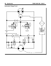
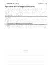
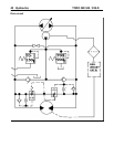
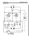
Hydrostatic Transmission Operation
Charge Circuit
The charge circuit supplies oil to the hydrostatic circuit and replenishes the oil normally lost through internal
leakage and transmission cooling.
1. Oil from the reservoir is drawn through the oil filter to the charge pump.
2. From the charge pump, the oil is exposed to the charge relief valve which maintains a charge pressure of 70
to 150 psi.
3. The oil then flows to the charge check valves.
4. The check valve that is in the low pressure, (non-driving) side opens and allows oil to flow to the drive loop.