


11
d B
kHz
m sec
COM
FAULT
KEYLOCK
EMERGENCY
EQ
COMP
GATE
DELAY
DUCK
NOM
LOUD
TONE
GAIN dB FREQQ
OL
0
–10
–20
–30
–40
OL
0
–10
–20
–30
–40
GAIN
REDCT
FADER
LEVEL
GAIN
REDCT
FADER
LEVEL
12345678
1234
5678
5533
15 16 18 1917
21 22 2320 2726 30 31 32
28 2924 25
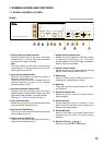
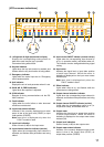
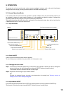
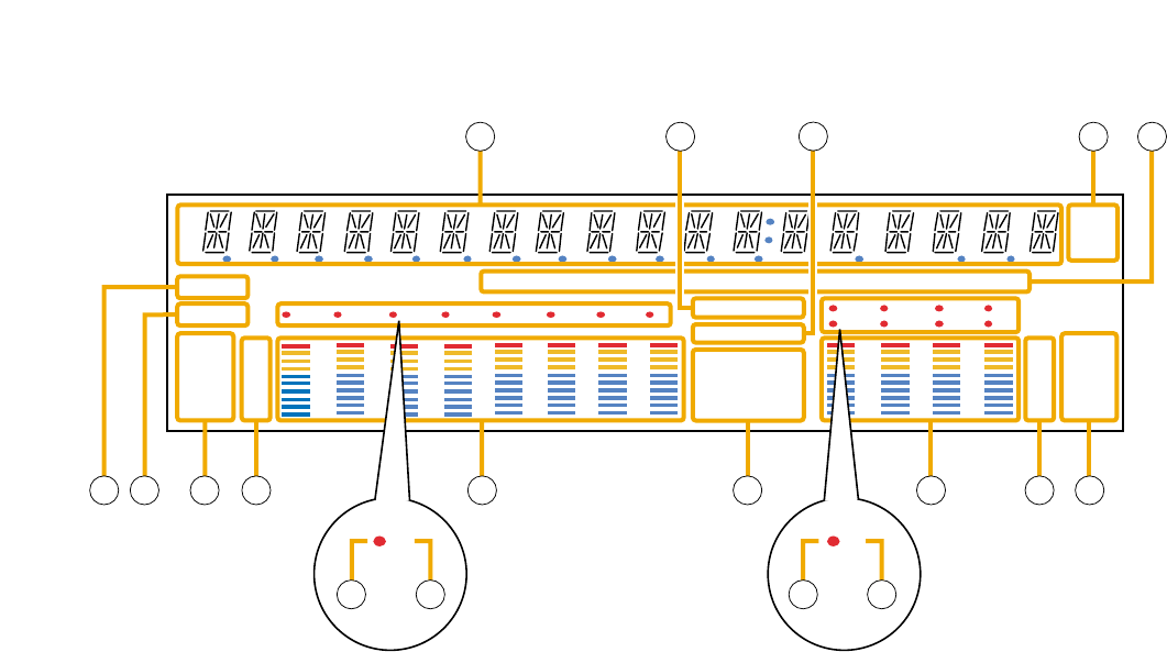
[VFD on-screen indications]
15. 14-Segment,18-digit alphanumeric display
Displays the corresponding setting screen or
data when each function key is pressed.
Parameters being edited flash.
16. Keylock indicator
Lights when the key lock function is enabled, and
flashes while the key lock function is being edited.
17. Emergency indicator
Lights when the control input set for "Emergency
mute" becomes active.
18. Unit indicator
Displays the unit of each parameter when it is set.
19. GAIN, dB, Q, FREQ indicators
Lights when the equalizer is adjusted.
20. COM indicator
Remains lit during communications via the RS-
232C interface.
21. Fault indicator
Lights when the unit's failure or other abnormal
conditions are detected.
22. Input meter status indicator
Indicates if the currently displayed input meter
status is that of the input level (LEVEL) or input
fader position (FADER).
Note: Input level is displayed only when the
D-001T module is used.
23. Input level indication
Scale of levels (in dB) for the input meter.
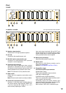
24. Input channel selection indicator (red dot)
Lights when the corresponding input channel is
selected, and flashes while parameters are being
edited.
25.
Input channel ON/OFF indicator (channel number)
Lights when the corresponding input channel is
on (i.e. in operation mode), and flashes when off.
The indicator remains extinguished during signal
muting.
26. Input meter
Indicates the signal level or input fader position
of each input channel. Which the meter is
indicating is displayed on the input meter status
indicator (22).
Note: Input level is displayed only when the
D-001T module is used.
27. Effect indicator
Lights when effect is on, and flashes while the
parameters are being edited.
28. Output channel selection indicator
Lights when the corresponding output channel is
selected, and flashes while parameters are being
edited.
29. Output channel ON/OFF indicator (red dot)
Lights when the corresponding output is on (i.e.
in operation mode), and flashes when off.
30. Output meter
Indicates the signal level or output fader position
of each output channel. Which the meter is
indicating is displayed on the output meter status
indicator (32).
31. Output level indication
Scale of levels (in dB) for the output meter.
32. Output meter status indicator
Indicates if the currently displayed output meter
status is that of the output level (LEVEL) or
output fader position (FADER).