


Quick Start List for Stand-Alone Operation
2-6
Evaluation Module Preparations
6) Adjust the source signal level as needed.
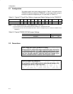
7) Use jumpers GAIN0 and GAIN1 to set the gain as shown in Table 2–5.
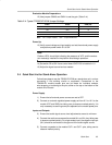
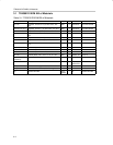
Table 2–5.TPA3001D1EVM Gain Settings
GAIN1 GAIN0 GAIN (dB)
ON ON 12
ON OFF 18
OFF ON 23.6
OFF OFF 36
Note: ON = Jumper installed, OFF = Jumper NOT installed
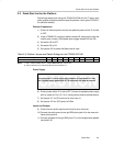
Control Inputs
Note:
The control signals applied to the EVM shutdown inputs must have sufficient
current capability to overcome the 120–kΩ pullup resistor on each input.
Holding down S1 places the amplifier in the shutdown state. Releasing S1
returns the amplifier to the active state.
Refer to the TPA3001D1 data sheet (SLOS398) for logic threshold voltage
ratings.
8) SHUTDOWN: This pin is active low. A low on this pin shuts down the ampli-
fier; a high on this pin places the amplifier in an active state. Leaving this
pin floating also allows normal amplifier operation.
Power Up
9) Verify correct voltage and input polarity and set the external power supply
to ON. The EVM should begin operation.
10) Adjust the signal source level as needed.