


Quick Start List for Stand-Alone Operation
2-5
Quick Start
Evaluation Module Preparations
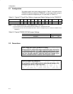
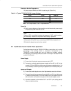
12) Use jumpers GAIN0 and GAIN1 to set the gain (Table 2–4).
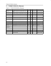
Table 2–4.Typical TPA3001D1EVM Jumper Settings
GAIN1 GAIN0 GAIN (dB)
ON ON 12
ON OFF 18
OFF ON 23.6
OFF OFF 36
Note: ON = Jumper installed, OFF = Jumper REMOVED
Power Up
13) Verify correct voltage and input polarity and set the external power supply
and platform power switch S1 to ON.
Note:
Platform LED1 should light indicating the presence of VCC, and the evalua-
tion module(s) installed on the platform should begin operation.
14) Set switch S2 to ON if tone control board SLOP109 is installed in U1.
15) Adjust the signal source level as needed.
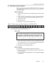
2.4 Quick Start List for Stand-Alone Operation
Follow these steps to use the TPA3001D1EVM as a stand-alone unit, or when
connecting it into existing circuits or equipment. Connections to the
TPA3001D1 module header pins can be made via individual sockets,
wire-wrapping, or soldering to the pins, either on the top or the bottom of the
module circuit board.
Power Supply
1) Ensure that all external power sources are set to OFF.
2) Connect an external regulated power supply set from 8 V to 18 V to the
module VCC and GND pins taking care to observe marked polarity. It is
only necessary to use the ground pins adjacent to the module power pins.
Inputs and Outputs
3) Ensure that audio signal source level adjustments are set to minimum.
4) Connect the audio source across the module IN+ and IN– pins, taking care
to observe marked polarity. For single-ended input, the negative input pin
(IN–) should be connected to the ground of the audio signal source.
5) Connect a speaker to the module OUT+ and OUT– pins, taking care to
observe marked polarity.