


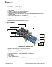
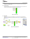
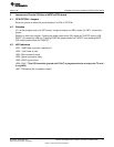

+
–
OUTB
OUT A
www.ti.com
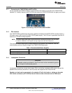
Installation
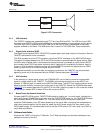
Figure 5. BTL Connection
2.1.4 USB Interface
The TAS5727 registers are accessed through I
2
C™ bus lines SDA and SCL. The USB circuit and USB
connector on the MC57xxPSIA board facilitates the connection between a host computer and the device.
The EVM USB circuit is powered by the 5V USB line of the host PC and is independent of the power
supplies available on the board. The USB device that is used is a TAS1020B from Texas Instruments.
2.1.5 Digital Audio Interface SPDIF
The Digital Audio Interface SPDIF (RCA/OPTO) accepts digital audio data using the I
2
S protocol. See the
TAS5727 data sheet for more information.
The RCA connector and the OPTO connector are the two SPDIF interfaces on the MC57xxPSIA board.
The switch S3 toggles between the OPTO and RCA connector to accommodate the signal source. When
the RCA cable or optical cable is connected and the signal source is powered up, verify that the SPDIF
lock indicator (blue LED5) illuminates, confirming that a viable signal is available to the device. Install a
jumper on JP4 across the middle pin and the pin marked SPDIF to connect the digital source to SDIN1.
Install a jumper on JP5 to connect the digital source to SDIN2.
For detailed information on how the data and clocks are provided to the TAS5727, see the schematic
appearing at the end of this document and the DIR9001 device data sheet (SLES198).
2.1.6 ADC Interface
In the absence of a digital signal source, the PCM1808 ADC can be used to convert an analog audio
signal to a digital signal to the TAS5727. The DIR9001 still provides clock signals to the ADC in this
process. A 12MHz crystal is installed on the MC57xxPSIA board. The ADC is an additional feature of this
board to provide flexibility in sourcing an audio signal to the TAS5727. Review the PCM1808 data sheet
(SLES177) for a detailed description of the ADC on this EVM. Install the jumper on JP4 across the middle
pin and the pin marked ADC to select ADC as the source for SDIN1.
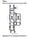
2.1.7 Board Power-Up General Guidelines
Connect theMC57xxPSIA and the TAS5727EVM boards by locating pin 1 on each board, indicated by a
small white triangle. TheMC57xx plugs down onto the TAS5727EVM board (i.e., the TAS5727EVM board
fits underneath the MC57xxPSIA board). Pin 1 on each board must be connected to each other.
Install the EVM software on the PC before powering up the board. After connecting the loudspeakers or
other loads, power supplies, and the data line, power up the 5V power supply first; then power up the
PVDD power supply. It is recommended initially to set the PVDD level to 10V, then ramp it up to 20V to
verify cable connections.
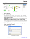
2.2 Software Installation
Download the TAS57x UI from the TI Web site. The TI Web site always has the latest release and any
updates to versions of the GUI.
5
SLOU299–December 2010 TAS5727 25W Digital Input Amplifier—with EQ and 2-Band DRC
Submit Documentation Feedback
© 2010, Texas Instruments Incorporated