


www.ti.com
Jumpers and Control Utilities on MC57xxPSIA board
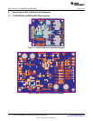
4 Jumpers and Control Utilities on MC57xxPSIA board
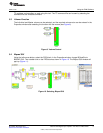
4.1 RCA/OPTICAL Jumpers
Select the jumper to reflect the source whether it is RCA or OPTICAL.
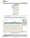
4.2 Switches
JP1 on the daughter card is for PBTL select. Jumper IN means non-PBTL mode. For PBTL, remove this
jumper.
Reset is an active-low function. Pressing the master reset switch (S2) resets the TAS5727 device; USB
RESET (S1) resets the USB bus. Pressing PDNZ (S4) powers down the TAS5727, and pressing MUTE
(S5) mutes (volume mute) the TAS5727.
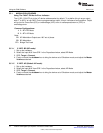
4.3 LED Indicators
LED1 : USB Power connector installed at J1
LED2 : 3.3V Power is valid
LED3: RCA connection made
LED4: Optical connection made
LED5: SPDIF signal locked
LED6: FAULT (This LED should be ignored until FAULT is programmed to be an output via I
2
C write
to reg 0X05.)
LED7: PDN switch (S4) is pressed (closed)
13
SLOU299–December 2010 TAS5727 25W Digital Input Amplifier—with EQ and 2-Band DRC
Submit Documentation Feedback
© 2010, Texas Instruments Incorporated