


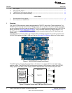
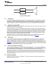

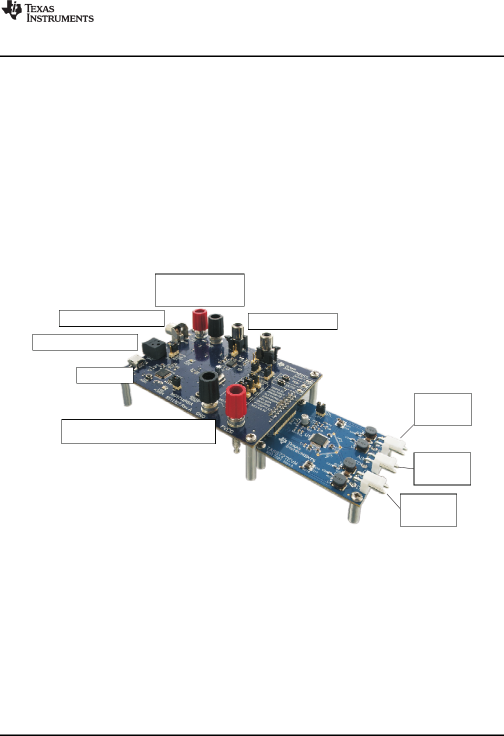
Analog In to ADC
Coaxial SPDIF Input
Optical SPDIF Input
USB Port
5V Supply for
System Power
8V–26V Supply for Output Power
Speaker
Out PBTL
Speaker
Out C & D
Speaker
Out A & B
www.ti.com
Installation
1.1 TAS5727EVM and MC57xxPSIA Features
• Channel evaluation module design
• Self-contained protection systems and control pins
• USB interface
• Standard I
2
S data input using optical or coaxial inputs
• Analog input through analog-to-digital converter
• Subwoofer connection—the PWM terminal provides the PWM signal and power to an external
subwoofer board
• Double-sided, plated-through PCB, 1oz copper, 2mm
• Access to control signal gain and data format through EVM-software GUI
2 Installation
This section describes the EVM and software installation.
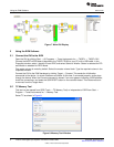
2.1 EVM Installation
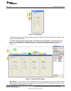
Figure 3. General Connection Picture
The following are the basic tools for the initial EVM power up.
• 5V, 1A power supply (VIN)
• 8–26V, 4A power supply (PVDD)
• Banana-plug test leads for power supplies and speakers
• Optical or coaxial cable for SPDIF interface based on signal source
• USB cable
• EVM software
• Two 8Ω speakers or loads
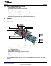
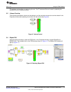
The following sections describe the TAS5727EVM board in regards to power supply (PSU) and system
interfaces.
3
SLOU299–December 2010 TAS5727 25W Digital Input Amplifier—with EQ and 2-Band DRC
Submit Documentation Feedback
© 2010, Texas Instruments Incorporated