


www.ti.com
3.2.3USBInterface
3.2.4DigitalAudioInterfaceSPDIF(J1/OPTO)
3.2.5ADCInterface
3.2.6BoardPower-UpGeneralGuidelines
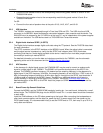
Installation
•ConnecttheleftspeakerwirestothecorrespondingmetalbindingpostsmarkedJ2andJ4onthe
TAS5601EVMboard.
•ConnecttherightspeakerwirestothecorrespondingmetalbindingpostsmarkedJ6andJ8on
TAS5601EVMboard.
ForSE:
•ConnectthefoursetsofspeakerwirestothepairsJ2-J3,J4-J5,J6-J7,andJ8-J9.
TheTAS5601registersareaccessedthroughI
2
CbuslinesSDAandSCL.TheUSBcircuitandUSB
connectorontheMC5601boardfacilitatestheconnectionbetweenahostcomputerandthedevice.The
EVMUSBcircuitispoweredbythe5-VUSBlineofthehostPC,andisindependentofthepowersupplies
availableontheboard.TheUSBdeviceusedisaTAS1020BfromTexasInstruments.
TheDigitalAudioInterfaceacceptsdigitalaudiodatausingtheI
2
Sprotocol.SeetheTAS5706datasheet
formoreinformation.
TheOPTOconnectoristheSPDIFinterfaceontheMC5601board.Whentheopticalcableisconnected
andthesignalsourceispoweredup,verifythattheSPDIFlockindicator(blueLED3)illuminates,
confirmingthatthereisaviablesignalavailabletothedevice.Installthefourclock/datajumpersacross
themiddlepinandthepinmarkedSPDIF.
FordetailedinformationonhowthedataandclocksareprovidedtotheTAS5601,seetheschematic
appearingattheendofthisdocumentandtheDIR9001devicedatasheet.
Intheabsenceofadigitalsignalsource,thePCM1808ADCmaybeusedtoconvertananalogaudio
signaltoadigitalsignaltotheTAS5601.TheDIR9001stillprovidesclocksignalstotheADCinthis
process.TheDIR9001oscillatorfrequency(Y2)determinesthesamplingfrequencyintheabsenceofa
digitalsignal.IftheOSCfrequencyis24MHz,thesamplingfrequencyissetat96kHz;ifOSCissetat12
MHz,thesamplingfrequencydefaultsto48kHzwhenthereisnosignalontheSPDIFinputterminals.A
12-MHzcrystalisinstalledontheMC5601board.TheADCisanadditionalfeatureofthisboardto
provideflexibilityinsourcinganaudiosignaltotheTAS5601.ReviewthePCM1808datasheetfora
detaileddescriptionoftheADConthisEVM.InstallthejumperonSDW2acrossthemiddlepinandthe
pinmarkedADC.
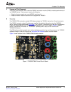
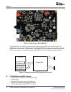
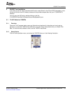
ConnecttheMC5601andtheTAS5601EVMboardsbylocatingpin1oneachboard,indicatedbyasmall
whitetriangle.TheTAS5601EVMplugsintotheMC5601board.Pin1oneachboardshouldbeconnected
toeachother.
InstalltheEVMsoftwareonthePCbeforepoweringuptheboard.Afterconnectingtheloudspeakersor
otherloads,powersupplies,andthedataline,powerupthe5-Vpowersupplyfirst;thenpowerupthe
PVDDpowersupply.ItisrecommendedinitiallytosetthePVDDlevelto10V,thenrampitupto20Vto
verifycableconnections.
TAS5601DigitalPowerAmplifierWithMC5601ModulatorKit 6SLOU219–February2008
SubmitDocumentationFeedback