


www.ti.com
3Installation
3.1SoftwareInstallation
3.2EVMInstallation
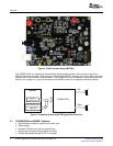
3.2.1PSUInterface
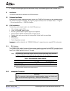
3.2.2LoudspeakerConnectors
Installation
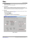
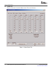
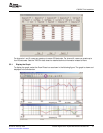
•AccesstocontrolsignalgainanddataformatthroughEVM-softwaregraphicuserinterface(GUI)
ThissectiondescribesthesoftwareandEVMinstallation.
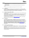
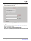
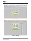
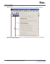
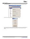
ExecutetheGUIinstallprogramsetup.exe,foundintheTAS570xGUIdirectoryintheprovidedcompact
disc.Oncetheprogramisinstalled,theprogramgroupandshortcuticoniscreatedinStart→Program
→TexasInstrumentsInc→TAS570xInterface.
ThefollowingarethebasictoolsfortheinitialEVMpowerup.
•5V,1Apowersupply(VIN)
•10–26V,4Apowersupply(PVDD)
•Banana-styletestleadsforpowersuppliesandspeakers
•OpticalcableforSPDIFinterfacebasedonsignalsource
•Coaxialcableswithphonoplugsforanalogaudioifdigitalaudioisunavailable
•USBcable
•EVMsoftware
•Two8-Ωspeakersorloads
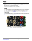
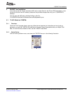
ThefollowingsectionsdescribetheTAS5601EVMboardinregardstopowersupply(PSU)andsystem
interfaces.
TheTAS5601EVMmoduleispoweredbytwopowersuppliesconnectedtotheMC5601controllerboard:
a5-Vpowersupply(VIN)anda10-Vto26-V(PVCC)powersupply.The3.3-Vlevelisgeneratedonthe
boardbyavoltageregulatorfromthe5-Vsupply.
Note:Thepower-supplycablelengthmustbeminimized.IncreasingthelengthofthePSUcable
increasesthedistortionoftheamplifierathighoutputlevelsandlowfrequencies.
Table1.RecommendedPowerSupplies
DescriptionVoltageLimitationsCurrent
(8Ωload)Recommendations
Systempowersupply5V1A
Outputpowerstagesupply10–26V4A
(1)
(1)
Theratedcurrentcorrespondto2channelsfullscale.
CAUTION
InBTLconnection,bothpositiveandnegativespeakeroutputsarefloatingand
maynotbeconnectedtoground(e.g.,throughanoscilloscope).
ForBTL:
SLOU219–February2008TAS5601DigitalPowerAmplifierWithMC5601ModulatorKit5
SubmitDocumentationFeedback