


PSU Interface (J901)
2-2
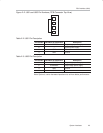
2.1 PSU Interface (J901)
The TAS5066−5111D6EVM module must be powered from one or two exter-
nal regulated power supplies. High audio performance requires a stabilized
output stage power supply with low ripple voltage and low output impedance.
Note:
The length of power supply cable must be minimized. Increasing length of
PSU cable is equal to increasing the distortion for the amplifier at high output
levels and low frequencies.
Maximum output stage supply voltage depends of the speaker load resist-
ance. Please check the recommended maximum supply voltage in the
TAS5111 datasheet.
Table 2−1.Recommended Power Supplies
Description Voltage Limitations
(4-W Load)
Current
Recommendations
System power supply 15 to 20 V 0.25 A
Output power stage supply 0 to 29.5 V 5.5 A
†
†
The rated current corresponds to 2-channel full scale (70 W each) or 6-channel 1/8 scale (9 W
each), which most likely is adequate for a standard 6-channel amplifier design.
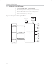
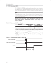
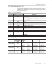
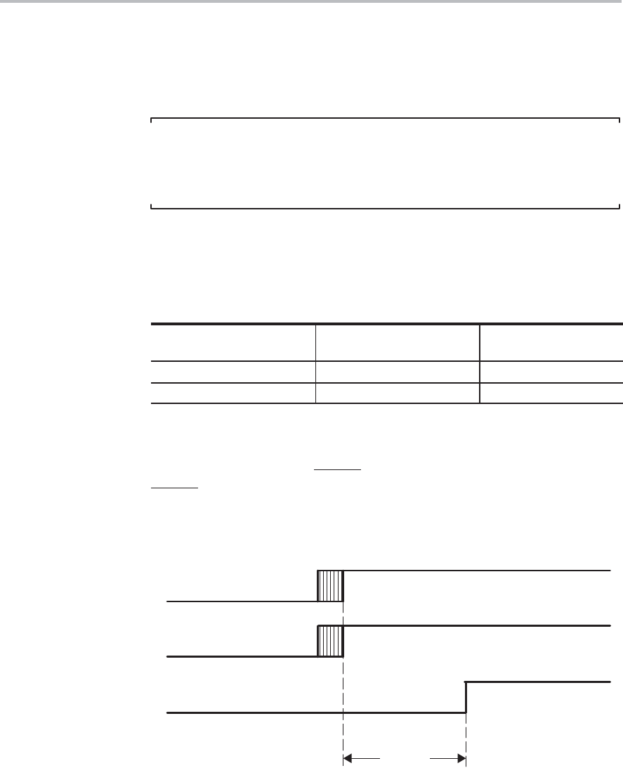
Figure 2−1 shows the recommended TAS5111 power-up sequence. For prop-
er TAS5111 operation the RESET
signal must be kept low during power-up.
RESET
is pulled low during power-up for 200 ms by the on-board reset genera-
tor (U903).
Figure 2−1. Recommended Power-Up Sequence
>1 ms
System power supply
Output stage power supply
RESET