


4-1
Power Supply Requirements
Power Supply Requirements
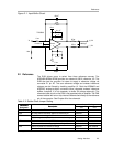
The EVM accepts four power supplies.
- A dual ±Vs dc supply for the dual supply op-amps. Recommend ±7 Vdc
supply.
- A single +5-Vdc supply for the analog section of the board (A/D +
Reference).
- A single +5-V or +3.3-Vdc supply for the digital section of the board (A/D
+ address decoder + buffers).
There are two ways to provide these voltages.
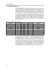
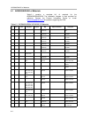
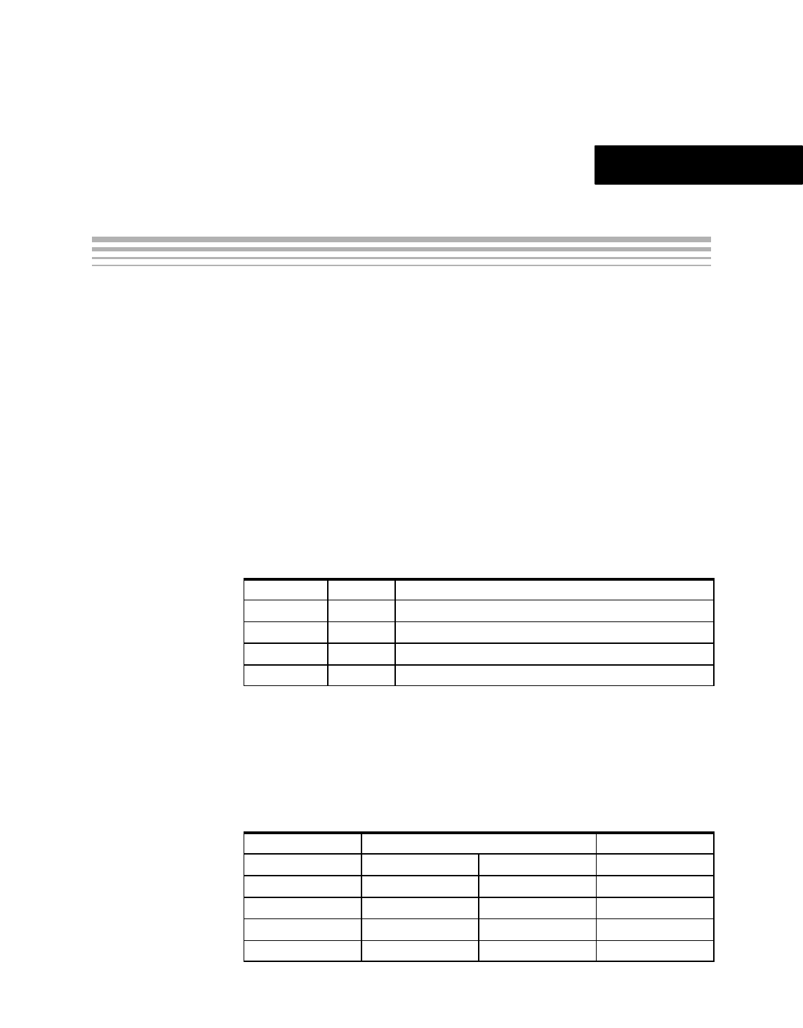
1) Wire in the voltages at test points on the EVM. See Table 4-1.
Table 4-1.Power Supply Test Points
Test Point Signal Description
TP14 +BVDD Apply +3.3 V or +5 V. See ADC data sheet for full range.
TP11 +AVCC Apply +5 Vdc.
TP12 +VA Apply +7 Vdc. Positive supply for amplifier.
TP13 -VA Apply –7 Vdc. Negative supply for amplifier.
2) Use the power connector J1 and derive the voltages elsewhere. The
pinout for this connector is shown in Table 4-2. If using this connector, set
the W1 jumper to connect +3.3VD or +5VD from connector to +BVDD.
Short between pins 1-2 to select +5VD or short between pins 2-3 to select
+3.3VD as the source for the digital buffer voltage supply (+BVDD).
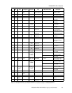
Table 4-2.Power Connector, J1, Pinout
Signal Power Connector - J1 Signal
+VA(+7V) 1 2 –VA (–7V)
+5VA 3 4 N/C
DGND 5 6 AGND
N/C 7 8 N/C
+3.3VD 9 10 +5VD
Chapter 4