


22
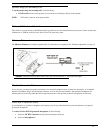
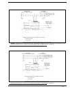
Step 2. Assemble the Faceplate to the Box
Use the four (4) screws supplied with the faceplate.
Step 3. Install the Intercom Station
Refer to the User Instructions for further information.
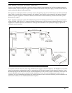
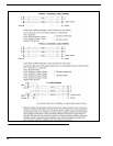
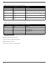
TABLE 4. SS2002 Wire Connection for use in Audiocom System
XLR Connector on Box Terminal Strip on Circuit Board Description
Pin 1 TB1-1 Common
Pin 2 No connection
Pin 3 TB1-3
Audiocom Channel 1 audio low and +24VDC phantom
power
Pin 4 TB1-4
Audiocom Channel 1 audio high and +24VDC phantom
power
Pin 5 TB1-5
Audiocom Channel 2 audio low and +24VDC phantom
power
Pin 6 TB1-6
Audiocom Channel 2 audio high and +24VDC phantom
power
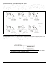
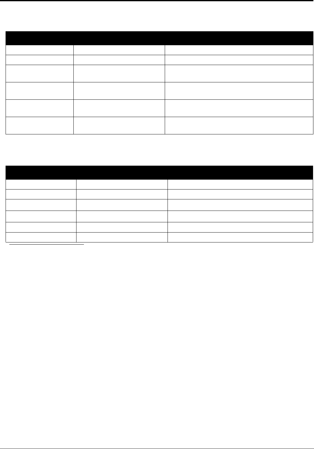
TABLE 5. SS2002 Wire Connections for use in Clear-com System
XLR Connector on Box Terminal Strip on Circuit Board Description
Pin 1 TB1-1 Common
Pin 2 TB1-3 Clear-com power input
Pin 3 TB1-6
Clear-com Line B
1
1. When connected as shown, Clear-com Line A corresponds to SS2002 Ch 1 and Clear-com Line B corresponds to SS2002 Ch 2.
Pin 4 TB1-4
Clear-com Line A
1
Pin 5 No Connection
Pin 6 No Connection