


21
APPENDIX A
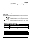
SS1002/2002 Supplemental Information
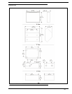
Installing the Box to the Faceplate
General Instructions
If you ordered SS1002/2002 boxes and faceplates separately, use these instructions to assemble the speaker stations. Once you
have assembled the stations, refer to the User Manual for all installation and operation information.
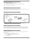
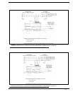
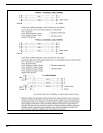
Step 1. Connecting the Wires from the Box to the Faceplate
Use the appropriate pin connections, see Table X, to connect the wires from the XLR audio
connector on the box to the terminal strip on the circuit board. (Or, in the case of the U box,
connect wires from the intercom system to the terminal strip.) To insert a wire into the
terminal strip, push back the green lever on the top of the terminal, as shown, then insert
the wire and release the lever.
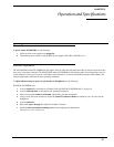
TABLE 2. SS1002 wire connections for use in Audiocom System
XLR Connector on Box Terminal Strip on Circuit Board Description
Pin 1 TB1-1 DC Common
Pin 2 TB1-3
Audiocom Channel audio low and +24VDC phantom
power
Pin 3 TB1-4
Audiocom Channel audio high and +24VDC phantom
power
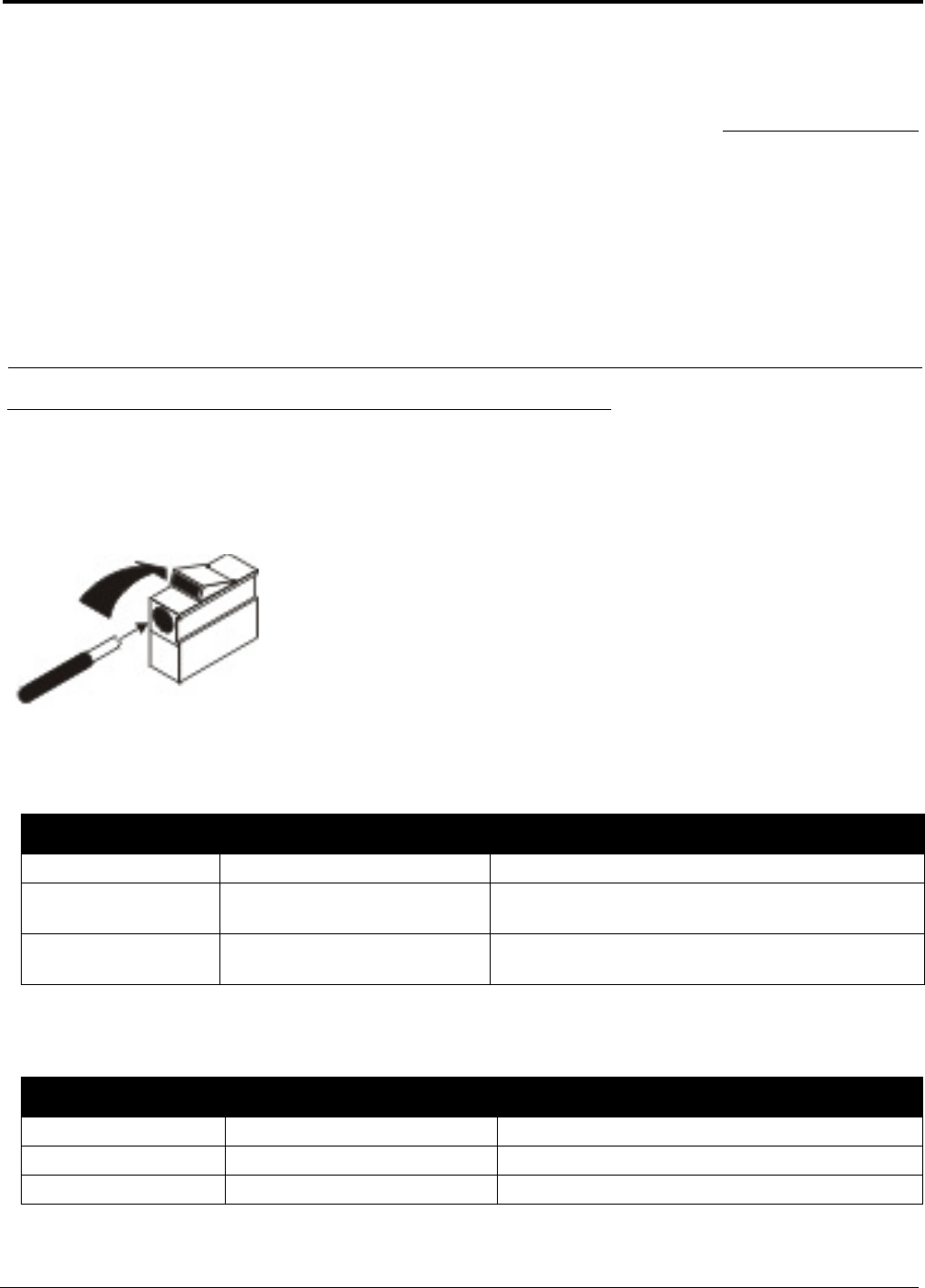
TABLE 3. SS1002 wire connections for use in Clear-com System
XLR Connector on Box Terminal Strip on Circuit Board Description
Pin 1 TB1-1 Common
Pin 2 TB1-3 Clear-com power input
Pin 3 TB1-4 Clear-com audio / call signal