


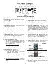
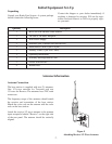
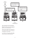
Base Station
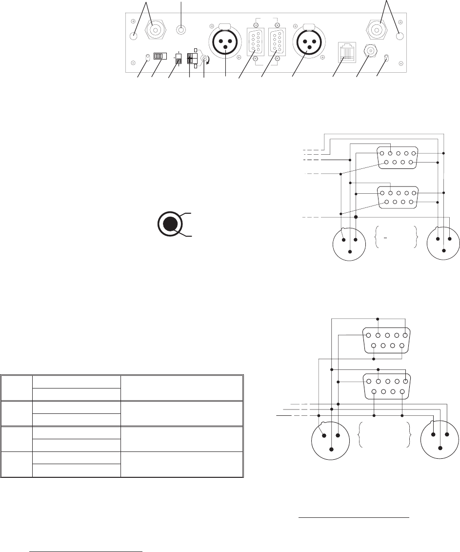
Controls and Connections - Rear Panel
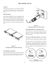
1. Transmit Antenna Jack - Color band on antenna must
match color dot on base station. Female “TNC” Connec-
tor.
2. Transmit Channel Switch - Changes frequency of
beltpack (shown on Serial No. Tag). Must match receive
channel on beltpack.
3. Audio Out - “RCA” type jack
provides a high impedance out-
put for an audio amplifier.
4. I/C Switch - Set for Telex or RTS type intercom systems.
See Figures 4 and 5.
5. Transmit Mode Switch -
A. “Remote” - The unit transmits only when the beltpack
is transmitting.
B. “Off” - The unit does not transmit.
C. “Continuous” - The transmitter is on continuously.
(Recommended Setting)
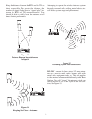
6. Dual Listen Switches
7. Dual Listen Level Control-Adjusts level of audio mix.
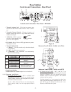
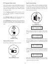
8.&11.Intercom 1 and 2 Jacks -
A. I/C Switch (#4) set to Telex
- “I/C 1" or ”I/C 2" (and
matching pins on jacks 9 and 10) are selected by the
Audio Channel switch on the front panel or the Chan
-
nel switch on the base station.
If one or both intercom lines are not used, plug the
Telex dummy load(s) into the appropriate unused
jack(s).
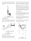
Figure 4
Intercom 1 and 2 Jacks - Switch set to Telex
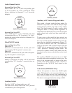
Figure 5
Intercom 1 and 2 Jacks - Switch set to RTS
B. I/C Switch (#4) set to RTS - “I/C 1" and ”I/C 2" are
connected in parallel (including matching pins on jacks
9 and 10). Channels 1 and 2 are selected by the Audio
Channel switch on the front panel or the channel
switch on the base station.
If neither channel 1 or 2 are connected to other inter
-
coms, plug the RTS dummy load into the “I/C 1 or 2"
jack. Do not use the dummy load if the unit is con
-
nected to an RTS intercom system.
-3-
AUX
ANT.
1
5
6
9
1
5
6
9
LOOP
THRU
I/C
BTR-600C
FCC ID. B5DM503
MADE IN U.S.A.
PATENT PENDING
TRANSMIT
AUDIO
OUT
TRANSMIT
CHANNEL
A
B
I/C 2
POWER
12-15V
AC/DC
RECEIVE
CHANNEL
A
B
RECEIVE
ANT.
I/C 1
TELEX RTS
I
/C
O
F
F
XMIT
MODE
REMOTE
CONT.
CH2+1
CH2+2
O
N
DUAL
LISTEN
LEVEL
PUSH
PUSH
1
3
15
2
4
5
6
7
8
9
10
11
12
14
13
Ground
Audio Out
1
3
2
1
3
2
1
5
6
9
1
5
6
9
PIN
1 GROUND
2 AUDIO
3 + AUDIO
(CHANNEL 1)
SWITCH #4
SET TO "TELEX"
I/C 1
(CHANNEL 2)
I/C 2
1
3
2
1
3
2
1
5
6
9
1
5
6
9
PIN
1 COMMON
2 CHANNEL 1
3 CHANNEL 2
IC/1
SWITCH #4
SET TO "RTS"
IC/2
Figure 3
Controls and Connections - Rear Panel - BTR-600C
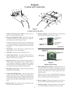
A. CH1+2=OFF Both audio channels are iso-
lated from each other.
CH2+1=OFF
B. CH1+2=ON Audio channel 2 is mixed into
channel 1.
CH2+1=OFF
C. CH1+2=OFF Audio channel 1 is mixed into
channel 2.
CH2+1=ON
D. CH1+2=ON Both audio channels are
mixed into each other.
CH2+1=ON