


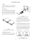
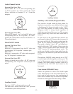
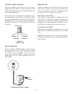
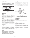
Auxiliary Audio Connection
The 6 pin telephone jack (RJ-11) may be used to
supply audio into and out of the base station. RTS
Matrix type intercoms may be interfaced to the base
station through this jack.
Since audio is not “Channelized” through this jack,
the audio channel switch has no effect on the audio
passed through the jack. The audio will be heard on
both channels 1 and 2 equally, audio generated by
the BTR on channels 1 or 2 will be sent to the Aux-
iliary Jack.
Figure 31
Auxiliary Jack
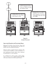
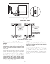
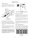
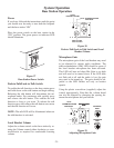
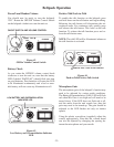
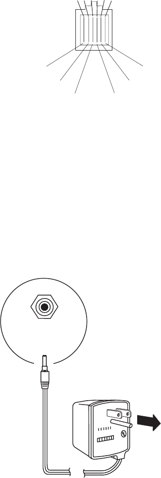
Power Connection
Insure the Power ON/OFF Switch on the front of
the base station is in the “OFF” position. Connect
the supplied AC power supply cord to the receiver
at the socket labeled “POWER”. Connect the power
supply unit to an AC outlet supplying 105 to 125
VAC, 60 Hz.
Figure 32
Connecting the Power Supply
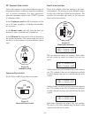
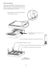
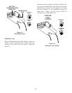
Dummy Load
In the case where a wired intercom will not be used
with the base station or only one of the audio chan-
nels are connected to the unit, it is important that
the dummy load(s) (supplied) be installed.
I/C Switch = Set for Telex
Telex dummy loads should be plugged into both
XLR ports if a wired Telex intercom system is not
being used. A single Telex dummy load should be
plugged into the unused channel’s XLR port if only
one channel is connected to an intercom system.
I/C Switch = Set for RTS
RTS dummy load should be plugged into one of the
XLR ports if an RTS intercom system is not being
used.
NOTE: If the dummy load is not placed properly,
an annoying squeal may result that may cause dam-
age to the ears.
-17-
NC
AUDIO IN +
AUDIO OUT +
AUDIO OUT -
AUDIO IN -
NC
PIN654321
TO
AC
OUTLET
POWER
12-15V
AC/DC